
Programming the D1 Mini (Clone) on Mac
Background:
The D1 Mini is a very popular hobby circuit with WiFi and an ESP8266 controller. They are used in robotics and environmental monitoring projects, as well as for holiday light displays! They are (almost) a drop-in replacement for ESPixelStick (and variants like the PIxelPop) developed by dedicated holiday light hobbyists. The nice thing is they combine WiFi and ESP on one board- no additional soldering required. (You do still need to solder a few connections to the board.)
I want to thank and give credit to a few sources, and everyone who is associated with them:
https://doityourselfchristmas.comhttps://diychristmas.comhttps://forkineye.com
Without these, and many others, all of those fancy over-the-top Christmas/Holiday light displays that are out there would probably be way too expensive and complicated for most people. This stuff still isn’t “easy” unless you want to pay a lot of money for pre-built controllers, like Light-O-Rama, which is still a great option if you have the money. It is a lot easier and less expensive than ever before thanks to these folks.
While most of what I post is redundant compared to other resources, I wanted to post what I am doing, and some of the ideas I have had, to hopefully add to what is out there in a positive way.
The big challenge I have had is that I run Macs exclusively at home. I use them for work, and it just made sense to use them at home too. There are some challenges using Macs because most of the development in this areas has been on PC/Windows. I could run Windows in a virtual machine or Boot Camp, but I wanted to be able to do this without such trickery. Fortunately- almost anything software you can get to compile in Windows can also compile in Linux and Mac OS, and there is some great light sequencing software (xLights) that does run natively on the Mac.
Another Mac challenge has been USB support for serial communications. The Arduino and DiY 3D Printer communities have dealt with this for many years now (I have a background in these as-well). Fortunately the latest Mac OS – Catalina, Actually comes with USB drivers for popular hobby chipsets. This tripped me up initially, because I installed 3rd party drivers on my Mac running Catalina without even testing things first- and I messed up the internal drivers. Fortunately I was able to uninstall them and get the stock drivers running again with an update.
So, without further ado, let’s get on to the D1 Mini…
First- there are a LOT of these out there- the original “WeMos D1 Mini” has been cloned by dozens of Chinese manufacturers, and they all work exactly the same. The only real difference is newer ones come with more onboard flash storage. You can buy then online through Amazon.com and ebay.com, or if you aren’t in a hurry- you can buy them a lot cheaper through popular Chinese resellers like:
https://banggood.com
https://aliexpress.com
Most Amazon and eBay sellers buy large lots of these electronics from China and resell them at a nice profit. If I have an urgent need to replace a failed board, power supply (PSU), or pixel string- I’ll order from Amazon or eBay and pay quite a bit more. Otherwise- I’ll order from China directly. The down-side to the latter is you can wait anywhere from 3-8 weeks (and sometimes longer) to get your order.
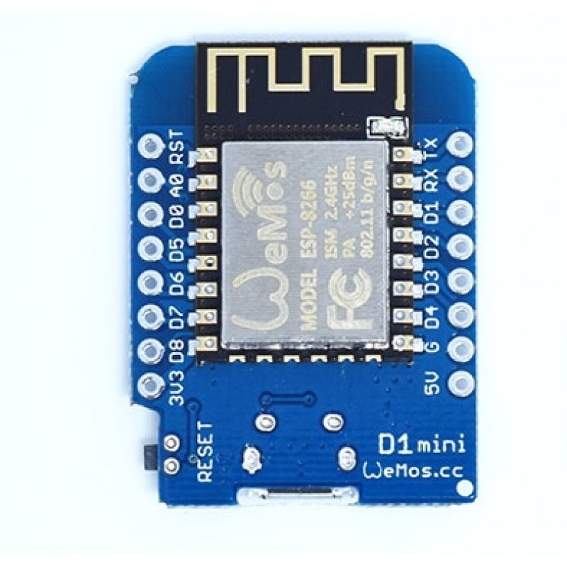
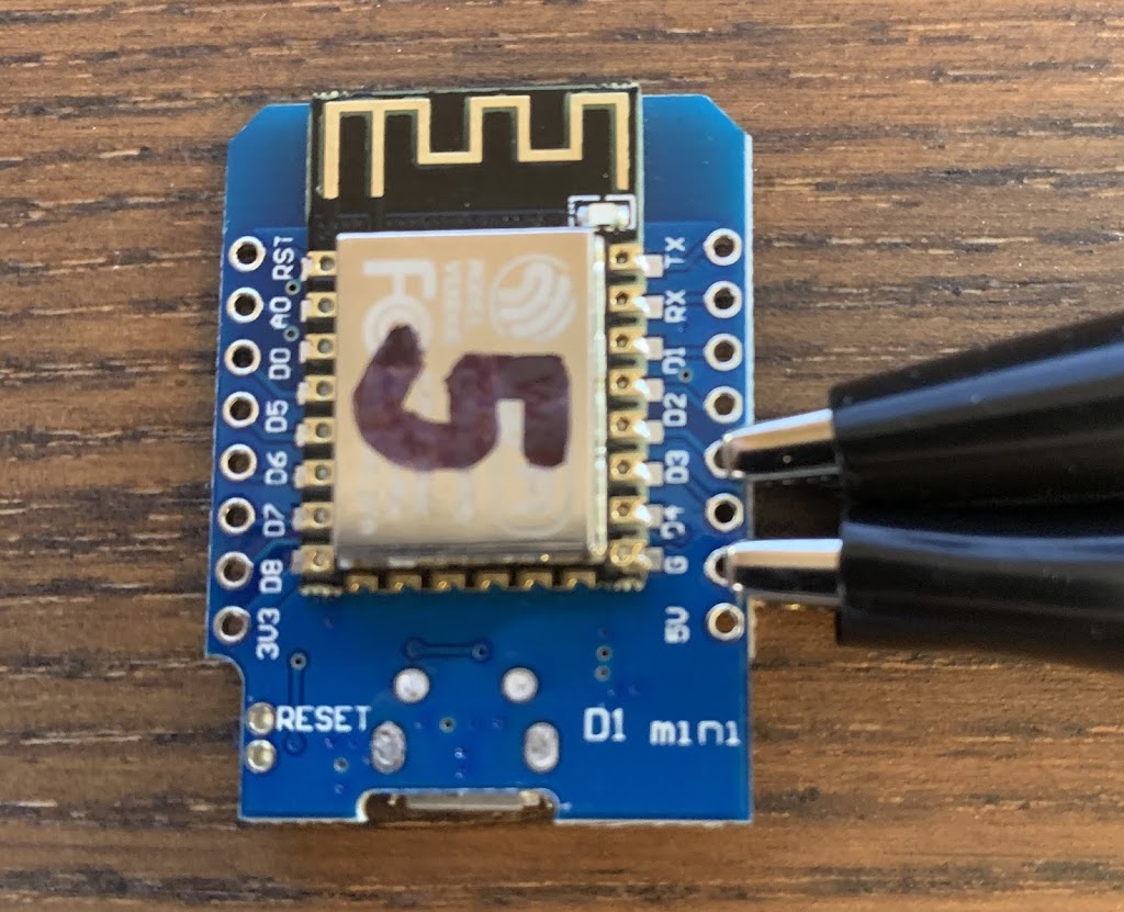
Regardless of where you buy, you are looking for one of these:

Look for “D1 Mini”. It will have an “ESP8266” microcontroller chip with built-in WiFi and a small WiFi antenna (look at the top of the picture above). It will have a micro-USB connector which is for programming and power, and will have a little reset micro-switch on the side. The board is just a hair under an inch wide, which is one of the reasons it is popular in the holiday light community- it can slide right in to 1” PVC, so the controller can actually be incorporated into a prop/decoration, or can be waterproofed inside a short section of pipe with two end caps.
In order to make it work as a pixel controller- we need to load the firmware on it. I’m going to cover this step-by-step for Mac, because the “easy” method of updating the firmware using a Java-based flash tool doesn’t work on a Mac. Even after installing Java and jumping through a bunch of Mac security hoops, the final firmware upload step is broken. All of the DIY tutorials I could find for programming the D1 use the Java firmware updater, so it’s very frustrating that it doesn’t work. Fortunately, while there are a lot of steps involved, you can compile and update the firmware yourself “the old-fashioned way”…
First- download and install the Arduino IDE. It’s available for Windows, Mac and Linux here: https://www.arduino.cc/en/Main/Software
Arduino is a hobby microcontroller series. They are great fun for a variety of projects like robotice, home automation, and 3D printing. But I digress… The IDE (Integrated Development Environment) is used to program Arduino and other microcontrollers. It’s relatively easy to use, and with a bit of tweaking- supports the ESP8266 chip based boards like the D1 Mini.
The Arduino IDE will install itself and set up a working folder, they call it a “Sketchbook”, usually in your “Documents” folder on your computer (I will assume Mac for the rest of this, but it could still be Linux or Windows). You can find the folder by launching Arduino and selecting “Preferences” from the Arduino menu. You can change the location if you would like, but otherwise- just remember where it is.
Next, go ahead and download the latest build of ESPixelStick firmware from:
https://github.com/forkineye/ESPixelStick
Click on the “Releases” link near the top of the file listing table. Find the first release with a green “Release” tag next to it. (It should say “Latest release”). Click the text next to it to open the “Assets” download links. As of this writing- I am using “ESPixelStick v3.1 Firmware”. As I said earlier- the pre-compiled firmware (“ESPixelStick_Firmware-3.1.zip”) doesn’t work on Mac, so you need to download the source code…
For a Mac- you can download using either “Source code” link, since Macs can work with either .zip, or .tar.gz files. Download the file and extract it to a folder. You should end up with an “ESPixelStick-3.1” folder (or similar as the version numbers will change).
Open the folder, enter CMD+A to highlight everything, and CMD+C to copy everything. Now- remember that Arduino folder in your Documents? Browse to that in Finder (or whatever folder Arduino is using as a “Sketchbook”). Create a new folder there called “ESPixelStick”. Open that folder up and CMD+V (Paste) all of the files you copied out of the ESPixelStick download folder. This creates a project folder for Arduino, which must match the name of the project itself.
Don’t dive into Arduino quite yet though. If you open the “README.md” file in a text editor, you will see there are a lot of prerequisites that we need to take care of first. This may seem a bit intimidating (it was to me, even though I’ve been doing things like this for years), but it isn’t too bad. There is some confusion because each project has its own, sometimes conflicting or confusing, instructions. I’m going to go through these one at a time…
Most of these are projects on Github, like the ESPixelStick firmware itself…
Aduino for ESP8266 – Arduino core for ESP8266
This actually tells the Arduino IDE how to “talk to” the ESP8266.
The important thing here is you don’t need to download or install it- the Arduino IDE will do that itself. If you scroll down on the download page- you will see detailed setup instructions. Really- all you need to do is this:
- Launch Arduino (if you don’t already have it running).
- In the Arduino menu- select Arduino -> Preferences.
- Scroll down to the field that says “Additional Boards Manager URLs”.
- In that field- cut (from here or the Web page) and paste:
http://arduino.esp8266.com/stable/package_esp8266com_index.json - Click on [OK].
Restart the Arduino IDE to load the new board configuration. Just go to Tools -> Board, and you should see “WeMos D1 R1” as an option. You can pick it now if you want, but we will get back to that later.
Arduino ESP8266 Filesystem Uploader – Arduino plugin for uploading files to SPIFFS.
SPIFFS is the file system used by the ESP8266. It actually stores Web pages used for configuring the device later. Don’t just download the current clone. If you scroll down through the README file- you will see a “release page” link.
- Download “ESP8266FS-0.5.0.zip” (or whatever the current release is).
- Unzip it into a folder in your Downloads.
- In your Arduino Sketchbook folder, create a new folder called “tools” (if it doesn’t already exist).
- Copy or move the unzipped folder (which should be called “ESP8266FS”) into this tools folder.
- You will end up with a path that looks like:
{sketchbook folder}/tools/ESP8266FS/tool/esp8266fs.jar - Restart Arduino again.
Under the Tools menu you should now see an option for “ESP8266 Sketch Data Upload”.
gulp – Build system required to process web sources.
This is where things get a bit more tricky. Gulp is used to process the Web pages that ESPixelStick uses. It uses Node.js, which must be installed on your Mac. You can find it here:
I always recommend installing the “LTS” version for safety.
Once Node.js is installed, you can install gulp through it by opening a Command Prompt (Terminal) and entering:
sudo npm install -g npm
sudo npm install -g gulp-cli
As long as you don’t see any abort/fail errors- you should be good. If you do- you may need to Google the errors as there could be some compatibility issue. I had an issue with Node.js because I apparently had an older version installed from a project a few years ago. The new install broke it. I found several resources online for completely removing all installs of node.js and installing again from scratch.
In addition to the above, you also need to install the following Arduino libraries. This is actually pretty easy…
Just download each of the following into your Downloads folder.
Then- in Arduino- select Sketch -> Include Library -> Add .ZIP Library
…and browse to and select each of your downloaded .ZIP files.
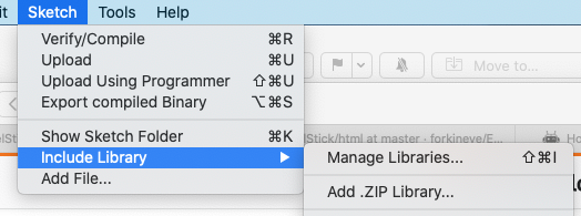

Arduino will unzip, verify, and copy the library files to its sketchbook libraries folder. You can also manually do this, but I’ve found this to be more reliable and fool-proof.
Here are the additional libraries you need to install:
- ArduinoJson – Arduino JSON Library
- ESPAsyncE131 – Asynchronous E1.31 (sACN) library
- ESPAsyncTCP – Asynchronous TCP Library
- ESPAsyncUDP – Asynchronous UDP Library
- ESPAsyncWebServer – Asynchronous Web Server Library
- async-mqtt-client – Asynchronous MQTT Client
Now we are ready to actually work with Arduino and the D1 Mini!
First, restart the Arduino IDE again, just to make sure everything is loading up right.
Now, go to Tools, Board. You should see a section for ESP8266. If not- double check your installation in the “Aduino for ESP8266” step above. Select “WeMos D1 R1” from the list.
Now you will see a bunch of new options now, related to this board…

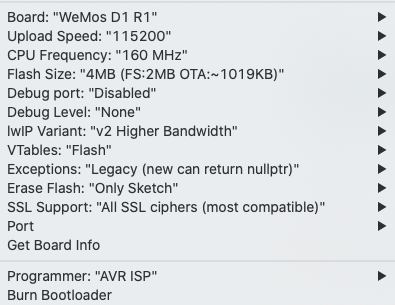
You should set yours up the same as the above. Important settings are:
Upload Speed: “115200”
CPU Frequency” “160Mhz”
Flash Size: “4MB (FS:2MB OTA:~1019KB)””
Note: You may have different options here depending on who made your D1. The important part is “OTA:~1019KB”.
Also, in case you use Arduino for programming any other boards- set Programmer: “AVR ISP” (I don’t believe this actually matters, but I had some issues with serial uploads before changing it.)
Now it’s time to actually load up ESPixelStick.
Select File -> Open and browse to the “ESPixelStick” folder you created earlier in your Arduino sketchbook folder. This should be ~/Documents/Arduino/ESPixelStick.
Double-click on “ESPixelStick.ino”. This will open the source code (Arduino calls this a “sketch”) for ESPixelStick. You will see that many other files (called includes) will open up as well in tabs. You don’t need to worry about any of these.
Just below the header information, you will see this:

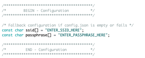
All you need to do is add your WiFi SSID and Passphrase where it says to. So, you may end up with something like…
const char ssid[] = “XmasLightsWiFi”;
const char passphrase[] = “MyWiFiPassword”;
Side-note: You can certainly use your regular old home Internet WiFi here for now, but when you do get around to running a light show- you want a dedicated WiFi network that probably shouldn’t be connected to the Internet or anything else but the computer you run your light show from. If you already have a “show” WiFi network- you can enter it here now. The nice thing about ESPixelStick is it will install a Web interface which will allow you to change the SSID and WiFi Password later if you need to.
Now save and compile your sketch. Just click on the checkmark button in the upper left corner of the Arduino IDE to run a test compile (Verify). If something goes wrong- make sure the “WeMos D1 R1” board is selected under Tools. 99% of compile errors (in my experience) come from having the wrong board selected. Double check the settings above as-well. Make sure you have quotes and semicolons in the right places!
Once you have verified that the sketch will compile, save it, and then get ready to upload it to the D1 Mini.
Update: For newer D1 Mini boards, this is not necessary. Only do the following “Programming Mode” jumper if you are unable to upload your sketch…
FIRST you need to put a jumper between G (Ground) and D3 on the board. This tells it to go into Programming Mode. l just use a jumper/test wire with small alligator clips for this. In a pinch you could solder a wire between them and then cut it later, but that makes a bit of a mess. Also note that I am not soldering headers on the D1 Mini. You only need to use 3 pins on it, so headers would be a waste of time and they take up unnecessary space, especially if you plan to mount your controller in 1” PVC.

Add your jumper BEFORE plugging it in to USB, and be very careful not to short any other pins!
Once you have done this- you can plug the board into your computer using a micro-USB cable.
Here is where things might get tricky for Mac. If you are running MacOS Catalina- you should be just fine- it already includes the USB drivers you need. Just check the Tools -> Port menu in the Arduino IDE…

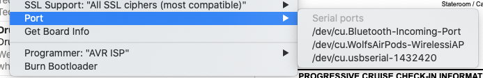
You should see something like: /dev/cu.usbserial-1432420
If you don’t- you may need to find and install a USB Serial driver. Before you do this though- try a different USB cable! If you are like me- you have a whole pile of them from various devices over the years. MOST of these may be charging-only cables! They don’t have data lines in them. I drove myself crazy for about six hours the first time I did this, because I “KNEW” I had the correct USB serial driver on my Mac, but couldn’t get any of the D1s to connect.
Update: I know at least for Catalina- the necessary USB driver is already installed.
Finding USB Serial driver software that actually works on a Mac can be a bit hit-and-miss…
Most of the D1s are made in China and use the same USB chipset. This driver works for many:
http://www.wch.cn/download/CH341SER_ZIP.html
(It’s a Chinese Web site- but look for “CH341SER_MAC_ZIP”
You can also try these:
https://github.com/adrianmihalko/ch340g-ch34g-ch34x-mac-os-x-driver
For some, this driver works too:
https://www.silabs.com/products/development-tools/software/usb-to-uart-bridge-vcp-drivers
If you run into driver signing issues or still can’t get it to work (and you have verified that your USB cable also does data)- you might consider paying for a signed/verified driver here:
https://www.mac-usb-serial.com
I know that’s a lot of options, but unfortunately dealing with USB Serial connections on a Mac can be very problematic. Anyone who works with Arduino, other microcontrollers, or who needs to use a serial adapter to communicate with network hardware knows this. Fortunately, as I said earlier- Mac OS Catalina should have the drivers you need built-in, so the above should only be necessary for older Mac OSs.
Once you are connected- select the serial port in Arduino under Tools -> Port (see above image).
Then just click on the little Upload arrow at the top of the Arduino window to compile and upload the sketch to the D1. If it doesn’t work- here are some things to try…
- Make sure the D1 is in programming mode. Double-check that you have a jumper between G and D3!
- Try pressing the Reset button, then try the upload again.
- Unplug everything, re-jump G and D3, plug USB back in and try again.
- If you use alligator clips to jump G and D3- you may need to fiddle with them a bit to make sure there is a good connection.
- Repeat the above a few times! Seriously- sometimes it just takes a few attempts.
You can verify that there is at least some kind of data connection by opening up Tools -> Serial Monitor in Arduino. Briefly press the Reset button on the D1 Mini. You should see some gibberish. Don’t worry that you can’t decipher what it is saying- if you see anything- you have a data connection. If you don’t see anything- some thing is wrong. If you have gone through all of the above an it just isn’t working- you may have received a dud board. Always order several- as some do fail out of the box. (They are dirt-cheap.) Try another one. If that one fails too- go through your whole setup again from the beginning. Once you have things working on one- you can revisit any “iffy” boards later.
Once you get the firmware uploaded- you aren’t done yet! You also need to configure and upload the Web interface to manage ESPixelStick…
Open up a command prompt on your Mac (Terminal), and enter the following:
cd ~/Documents/Arduino/ESPixelStick/html
gulp
The gulp utility will essentially build a tiny Web site for ESPixelStick and prepare it for upload to the D1 Mini. If gulp doesn’t work- you may need to double check the install of Node.js and gulp that we did earlier. It should exit without any errors.
You can close the Terminal window now.
Click on Tools -> ESP8266 Sketch Data Upload
This will upload the Web configuration site from the “data” folder that was populated by gulp in the previous step.
If there is an upload error- you might need to double check (again) that the D1 is in programming-mode and properly connected by USB. You may need to unplug and plug it back in again. Also- again- make sure Serial Monitor isn’t open.
Once the upload is successful- go ahead and open Tools -> Serial monitor again.
Unplug the D1 Mini from USB, and disconnect the programming jumper.
Plug the D1 Mini back into USB.
Watch the Serial Monitor. You should see something like…
{initial connection gibberish}
ESPixelStick v3.1 (Jan 15 2020)
SDK:2.2.2-dev(38a443e)/Core:2.6.3=20603000/lwIP:STABLE-2_1_2_RELEASE/glue:1.2-16-ge23a07e/BearSSL:89454af
File system initialised
Total bytes in file system: 59487
/www/esps.js.gz42348
/www/esps.css.gz10163
/www/index.html.gz3969
/config.json1263
– Configuration loaded.
– Listening for 1500 channels, from Universe 1 to 3
Connecting to XmasLightsWiFi as null
Connecting with DHCP……………
Connected with IP: 192.168.1.152
IP : 192.168.1.152
Subnet mask : 255.255.255.0
– Web Server started on port 80
– E131 Unicast port: 5568
– DDP Enabled
ZCPP subscribed to multicast 224.0.31.14
– ZCPP Enabled
– ZCPP Subscribed to multicast 224.0.30.5
Don’t worry about most of this for now- you will likely see slightly different things anyway. What you want to look for is the IP: xxx.xxx.xxx.xxx line. In the above example- IP: 192.168.1.152.
On a computer connected to the same WiFi network- open up a Web browser and type in that address. (in some browsers- you may need to enter “http://“ first, like: http://192.168.1.152 (The web page isn’t secure.)
If everything went right- you should see a great little configuration Web page for your ESPixelStick. Here you can set things like the SSID and Password for your actual show WiFi network, you can rename the controller, change the DMX universe and number of channels, and set up an initial/idle display, which is also great for testing your pixels. I’ll cover more on all of this later- for now- just make sure the page loads.
You can see if the controller is working by going to Effects and setting something like “Rainbow”, and then click on “Diagnostics” and you should see a rainbow pattern displayed (without even connecting anything yet).


You will need to do a couple more things to have an actual operational controller, and it involves some soldering.

You only need to solder/use these three pins. If you run 5v pixels- you just need to connect the D1 Mini to the same 5v PSU that you run your pixels from. If you run 12v pixels- you will need to use a buck converter (12v-to-5v adapter) to connect the D1 Mini to power. Suitable buck converters can be had for a few dollars a piece (much less if ordered directly from China. The board will look something like this:

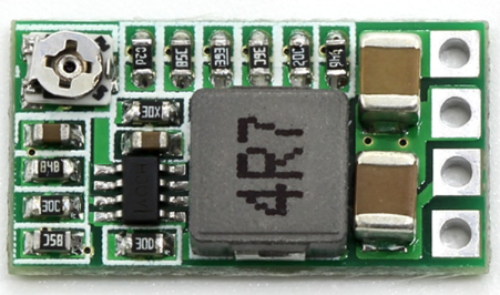
The terminal positions will be marked, usually on the back, for 12v input and 5v output. Solder and connect carefully. If it is adjustable like this one is (small potentiometer in the upper-left corner fo the picture), you WILL want to hook it up to a voltmeter and make sure it is right at 5v. (Never assume they are set for the right voltage from the factory- they won’t be.)
Again- you only need this if you are running the D1 Mini on a 12v system.
There are a couple of commonly-recommended things I have found online that don’t seem to work for the D1 Mini. Of course your mileage may vary, so-to-speak, and you may just need to experiment like I have. These could depend on the manufacturer of the pixels and power supply (PSU) you are using.
The first is most guides recommend bridging your power connection with a 1000Mf or larger electrolytic capacitor. This just didn’t work for me at all. For some reason my pixels flickered very annoyingly, even with a static (not-moving) display. I use high-quality Mean-Well PSUs that already have very large internal capacitors for filtering/smoothing-out the power, so the capacitor was redundant anyway. So- I took it out of my design.
One thing you DO need is a resistor between Data-Out on the D1 and Data-In on your pixels. Most guides recommend 300-400ohm, but I have found that to be way too much for the D1 Mini’s digital output. At 300 ohms- my pixels didn’t receive any data at all. Through a lot of trial and error- I found a 100ohm works best. If you don’t put a resistor in the data line- you may end up with unwanted randomly flickering/flashing pixels, or even out-of-place pixels with shifted designs. Too much resistance and they just won’t work at all. You may need to experiment though- if you have a long data cable (more than 5′ or so) you may not need a resistor at all as the cable’s resistance will be enough.
Here is an early drawing of my setup. It has a glaring error- which I will fix in future revisions. The D1 Mini uses D4 for Data, NOT D5 as show below. I had found some bad information online when I first set out to draw the diagram.

I’ve made some changes to how I run things now too- no longer separating PSU and controller. More on that to come…