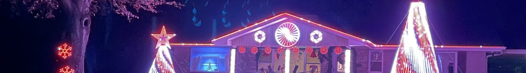
Pixel Data Cables
I’ve seen a lot of debate about this, and of course everyone does things differently. I just wanted to show what I am doing for my cables this year.
So- you have a fancy new controller, like a Kulp K16A-B:
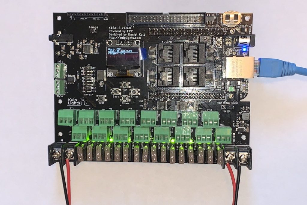
You stick it in a box with power supplies, terminal blocks, and maybe an FM transmitter and WiFi. Now what? You need to get data and power to your pixels! Pixel data is precious in our world, and unfortunately it is short-lived and can’t travel far.
A lot of people try to get power and data in the same cable to the pixels. This creates problems because you need at least 3 conductors, and the power conductors need to be fairly large. You can also generally only go about 15-20 feet with standard cables reliably because the data will degrade. Unless you have thick cables (low gauge)- DC voltage will also degrade quickly due to voltage drop. There are pre-made cables/extensions using proprietary connectors, like “xConnect” or “Ray Wu”. A lot of people like these because they are plug-and play, but they still have the same length limits.
Some folks use “Alarm Wire”, which is generally a good choice. It can be had in thicker 18-20 gauge wire sizes, and can be bought with only 3 conductors, which is what we need. Still- the wire distance remains the same- it doesn’t matter how thick your conductors are- WS2811 (or any serial data) just can’t travel very far on straight conductors.
Enter Cat. 5e or Cat. 6 Ethernet cable. It is usually significantly cheaper than other cables because it has become a commodity, and most-importantly- it is made for carrying data, and does it very well. These cables use carefully twisted pairs of wire. The twists help prevent interference to the data signal, and help maintain its integrity over longer distances. Each pair of conductors uses a different twist, so they also won’t interfere with each other if multiple pairs are used for data (as in Ethernet, and for differential data).
I plan to cover differential data in a separate article in the future. If you have wired controllers- you will very likely end up using differential senders and receivers. They allow you to greatly expand the reach and versatility of your controllers. Most controllers (such as those from Kulp, Falcon, and Hanson) have differential transmitter/senders built-in, or have differential expansion boards available. These allow you to extend your pixel data network up to 300′ or more. Hansen Electronics has differential senders and receivers that claim up to 250m (800+ feet) of transmission distance! But, I digress…
Differential data needs Ethernet cable, so you will eventually need to pick up a box of it anyway. Why not just use the same cable for your regular pixel data? There is really no reason not to.
As I said earlier, WS2811 data is very tricky and based entirely on timing- so it is corrupted/degraded very easily. Generally you can’t go much further than 15-20′ with standard straight-wire connections, although some have been lucky enough to push it to 50′. Different pixel manufacturers use different chip manufacturers and different grades of wire, and some have sketchy solder joints. All of these things affect how long of a data run you can make.
There are methods of extending the data, using “null pixels” and pixel amplifiers (“F-Amps” are Falcon’s version). These re-generate the signal so it can travel farther. These work but just give you more hardware to deal with and another point of failure. Recently Falcon had to recall a production run of their F-Amps due to a manufacturing problem. The timing (September-October) was pretty bad. Not really their fault- things like that happen, but if you have a display dependent on them and they are recalled or fail- you have a problem.
Ethernet cable allows you to extend your pixel data beyond 20′, to 50′ or even further. I’ve seen test runs of 100′ online, and have heard of real working installations of 70′. Again- there are a lot of variables in-play, but you should be able to get at least 50-100% more distance out of Cat. 5e or Cat. 6 cable than straight-conductor cable under the same conditions.
The down-side is the conductors are only 22 gauge wire, so they can’t carry a lot of power. Power over Ethernet is a thing, but it is strictly limited to prevent damage to the cable, and a desk phone or WiFi AP use significantly less power than a strand of pixels. The Power over Ethernet standard also compensates for voltage drop automatically, which we can’t really do with our pixels. So- while we can send some power down the cable, we can only really power about 50-75 pixels with it safely. (Technically it should be able to handle 100, especially because we are bundling multiple conductors, but I personally think pushing these cables that far is a bad idea.) Of course we also have to consider voltage drop, so again- every situation is different. If you have smaller props with only around 50 pixels or less- the Ethernet cable may be all you need. Larger props and strings will need power injection- but they need that anyway!
I use Cat. 5e and Cat. 6 cable to run data to my pixels. I had boxes of each, and don’t really feel there is much difference between the two for this application. I run power through it too, but only count on it for around 50 pixels. I run separate power cables for anything more than that (which is pretty much everything). I use the same cable for runs between props too.
I only use one conductor for data, and the rest are for power and ground. There is nothing wrong with doing this for DC power. You should never run multiple (separate) conductors for AC power, audio, or serial data. The reason is slight differences in the length and construction of the conductors can lead to phase issues over the length of the cable. This can cause really big issues with data and AC power. There are no phases to worry about in DC.
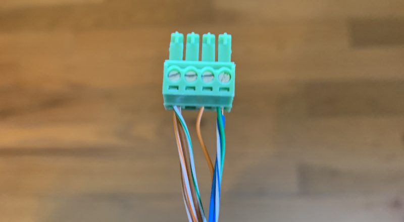
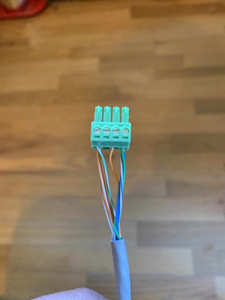
Here is how I use the conductors in Ethernet (Cat. 5e or Cat. 6) cable for pixels:
Note: I updated this in 2021 so it makes a bit more sense and is easy to identify and connect the power wires. I admit I made things too complicated the first time I did this. This is not reflected in the pictures I have posted in the rest of this article. All of the “white” wires are ground, and the non-orange solid colored wires are Vcc(+).
Orange – Data
Orange/White – Ground
Green – Vcc (+)
Green/White – Ground
Blue – Vcc (+)
Blue/White – Ground
Brown – Vcc(+)
Brown/White – Ground
There are as many ways to do this as there are conductors in the cable. Again- you want to be sure to only run ONE conductor as data, and the other half of that pair needs to be grounded. This provides the shielding for the data. Most people use the orange or green pair for this. Some use the white half instead of the solid. For me, as an old electrician, white designates common or ground, so I like using it as the ground side. In telecom and networking- white is primary, so from that world it makes sense to go with Orange/White for data. Either way- you just need to be consistent!
I remember this scheme in-line with EIA/TIA 568B, which is used for Ethernet cabling. The general color order from left to right is Orange, Green, Blue, Brown. (Green is split over Blue, for when you start making your own cables.) I do solid orange for data (instead of white-orange), so the white half goes to ground. I split Green between Vcc and Ground. Now I want more Vcc- so both Blue wires go there, and then Brown is, well, ground. That’s just how I remember it! 🙂
Here is what it looks like in-practice:
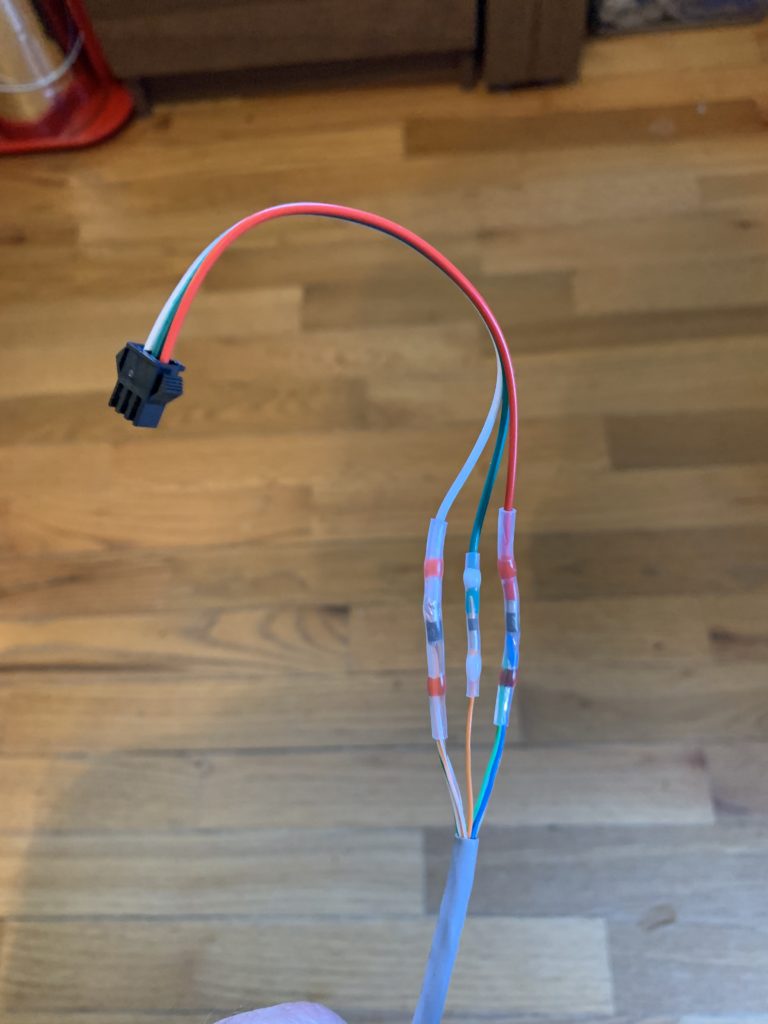
So- what do I gain from all of this? Well- I can easily go over 25′ with one of these cables, much further than straight-wire ones, without needing null pixels or a pixel amp. I’m also using cheap/stock cable that I can buy at any hardware store or home center. A 20′ X-Connect “Extension Cable” costs around $9.00, but 20′ of Cat. 5e costs less than $1.50! Best of all- I can make the exact length of cable I need- no coils of excess cable anywhere, and no worries about whether or not I have a long enough extension cable, or having to move a prop because a pre-made cable doesn’t quite fit.
For power injection- I use a mix of 16 gauge outdoor-rated speaker wire, and regular-old 14 gauge “zip cord” speaker wire. The latter might not last as long exposed to sunlight (I’ll know more after this season). I have some 14 gauge “landscape wire”, which is also highly recommended by others, but have not had to use it yet. It is my back-up in case the 16 gauge doesn’t hold up. So far I haven’t had any issues though.
Quick update (2021):
The outdoor rated speaker and landscape wire I used doesn’t show any signs of wear at all after being out in the sun for a couple of months. The “zip cord” speaker wire clouded up a bit, but is still in-tact and flexible. I don’t think it will last more than a couple of seasons, but I’m going to see how long it actually lasts. It’s cheap and easy to work with, so has that as an advantage. Truth be told- the pixel wires themselves were also visibly faded. This year I’m also trying out some silicone-jacketed 14Ga automotive speaker wire. It’s thinner and more flexible than the landscape wire, and was less than half the cost.