Column Matrix Builds
Last year, we lit up two of our three front porch columns with PVC pixel “poles”. These worked really well: Pixel Columns
This year we are making several changes. First, we got rid of the flat-tree in the middle of the front of the porch, so I needed to light up the middle column. Second, my lovely wife planted some new shrubs in front of the porch, which will end up growing in front of the columns.
I decided I wanted something that sat up higher, but made up for being shorter by having more detail. After working on the P10 Info Matrix earlier this year for the carport, I decided to do P10 displays for the columns as-well!
I decided to take what I learned doing the Info Matrix and extend it to make the lightest, cheapest, simplest, weatherproof (hopefully) P10 displays I could. This will likely be a controversial build, and I don’t know how well it will hold up, but I’m going for it anyway.
First, I want to say up-front as a bit of a disclaimer- I’m using “Indoor” P10 panels for this build. Many folks do, as they are significantly cheaper and easier to work with than the “Outdoor” ones. I’ve also found this year (2021) in-particular that the Outdoor ones are hard to come by, with major vendors sold out of them. In any case- they need to be protected from the weather and any use outdoors, regardless of how they are enclosed, voids their warranty.
I decided I wanted to do 5-panel long columns, which are about 5’4″ long once assembled. I used 3D printed panel connectors, which are similar to those you can buy from several vendors who also sell the panels. I highly recommend Wired Watts for panels and related supplies. If you have a 3D printer, you can find the STLs for the connectors here: https://www.thingiverse.com/thing:3467487
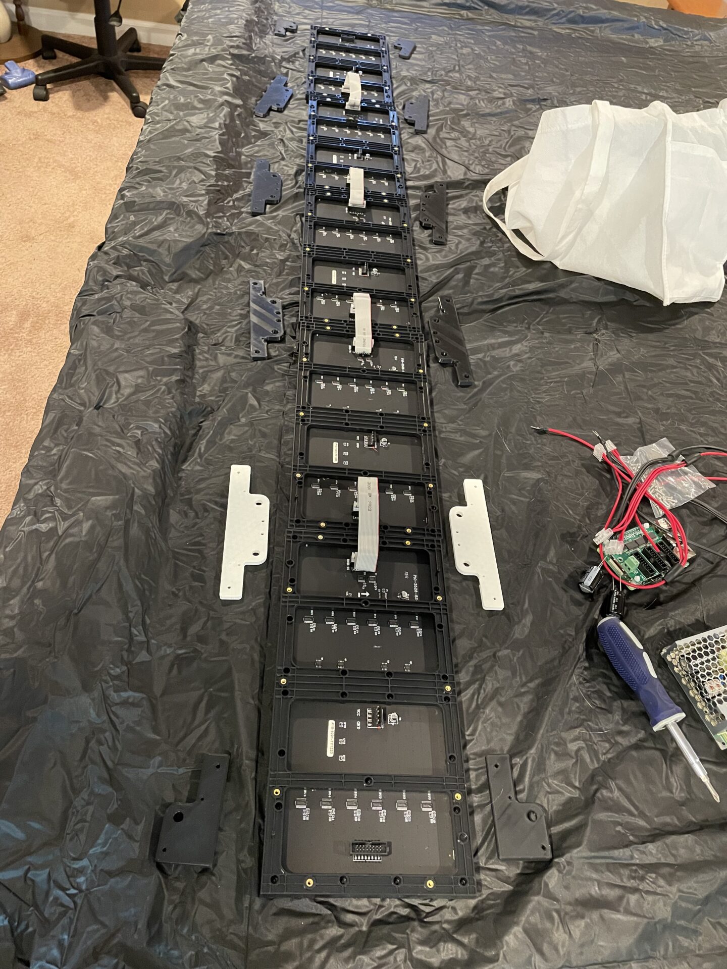
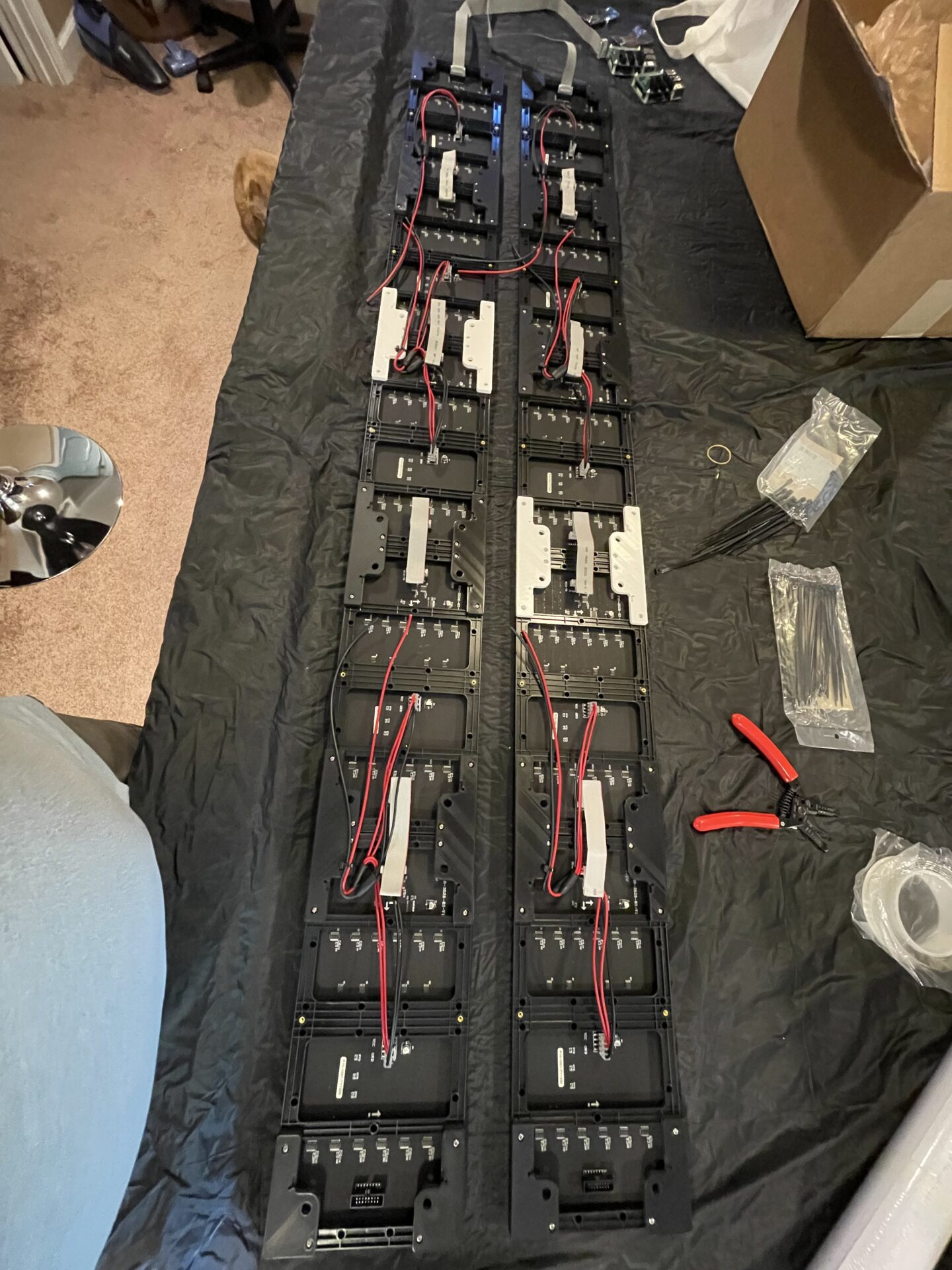
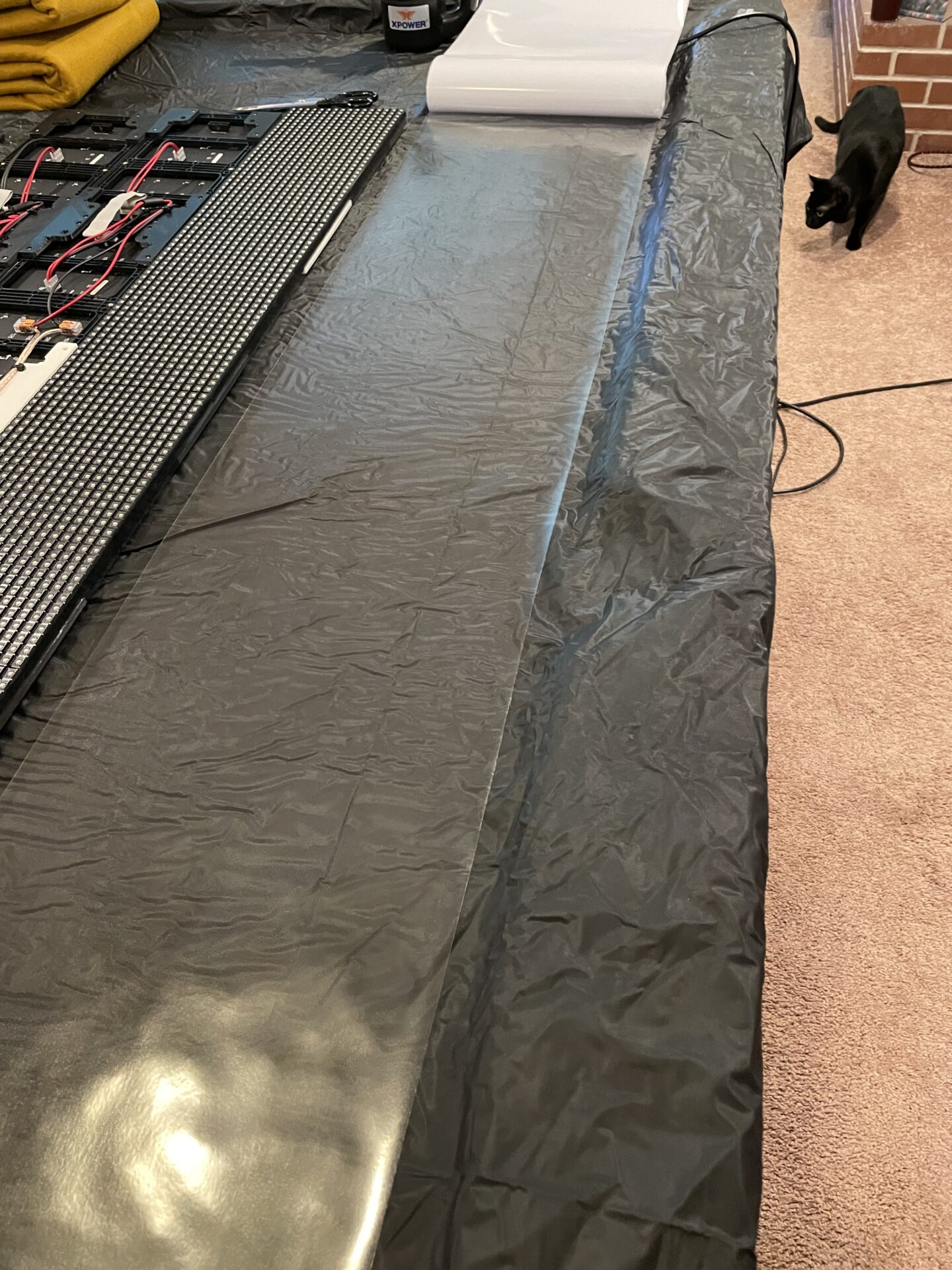
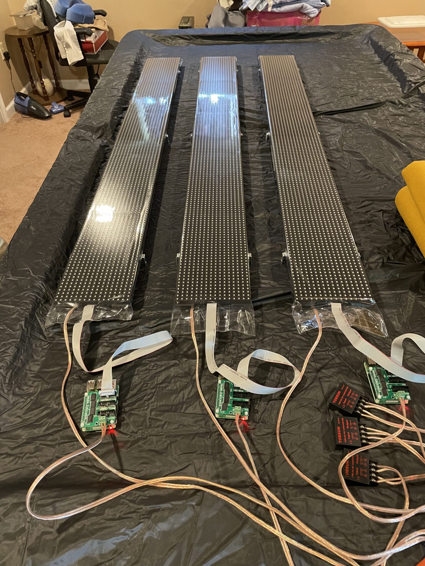
For each column- I laid out the panels and connectors to begin assembly:
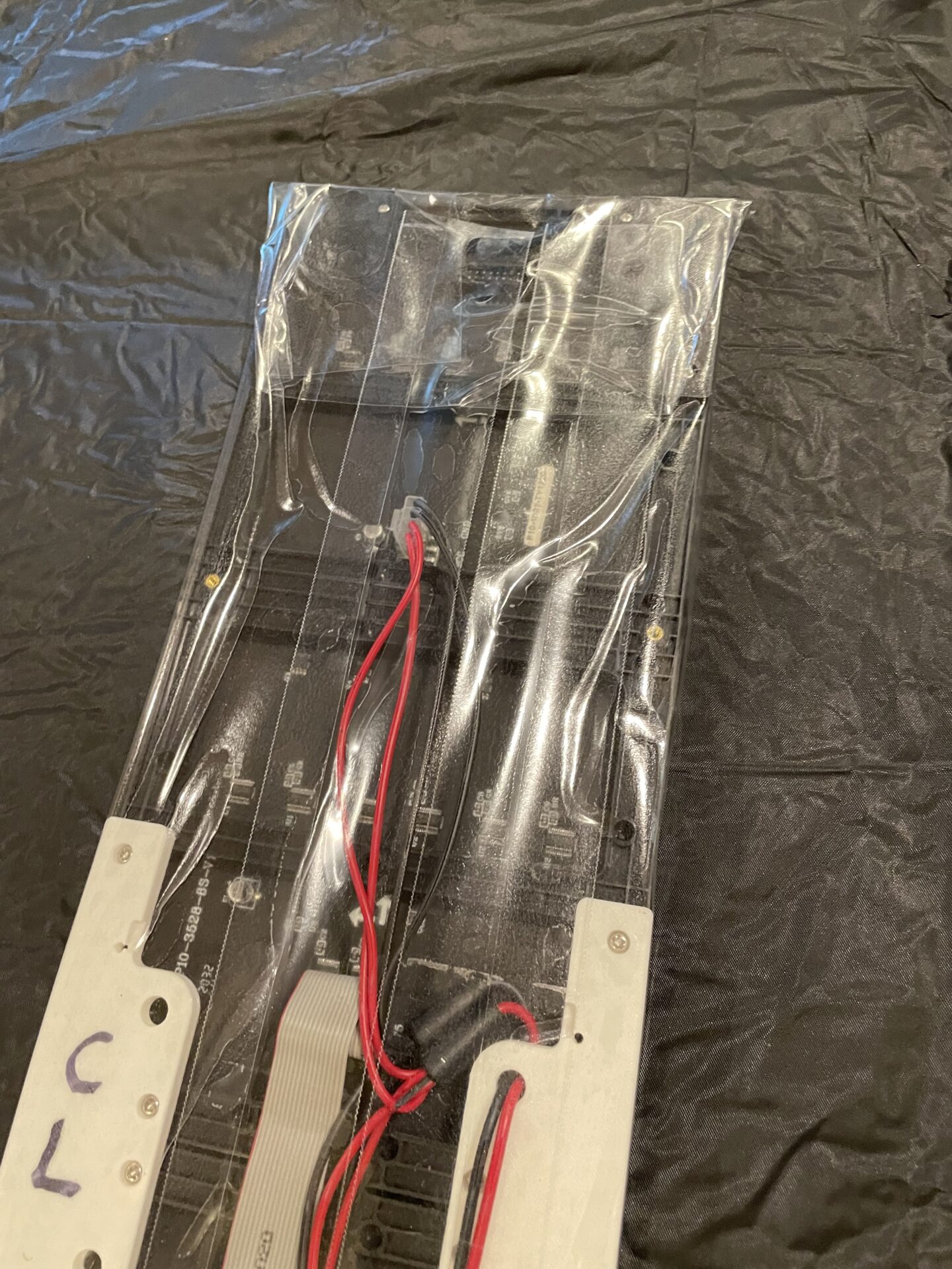
Note there are white connectors. This was actually just because I ran out of black filament, and had a spool of white handy. I’m actually using them as a quick indicator of which column each panel is for, but that’s a bit irrelevant to the overall build.
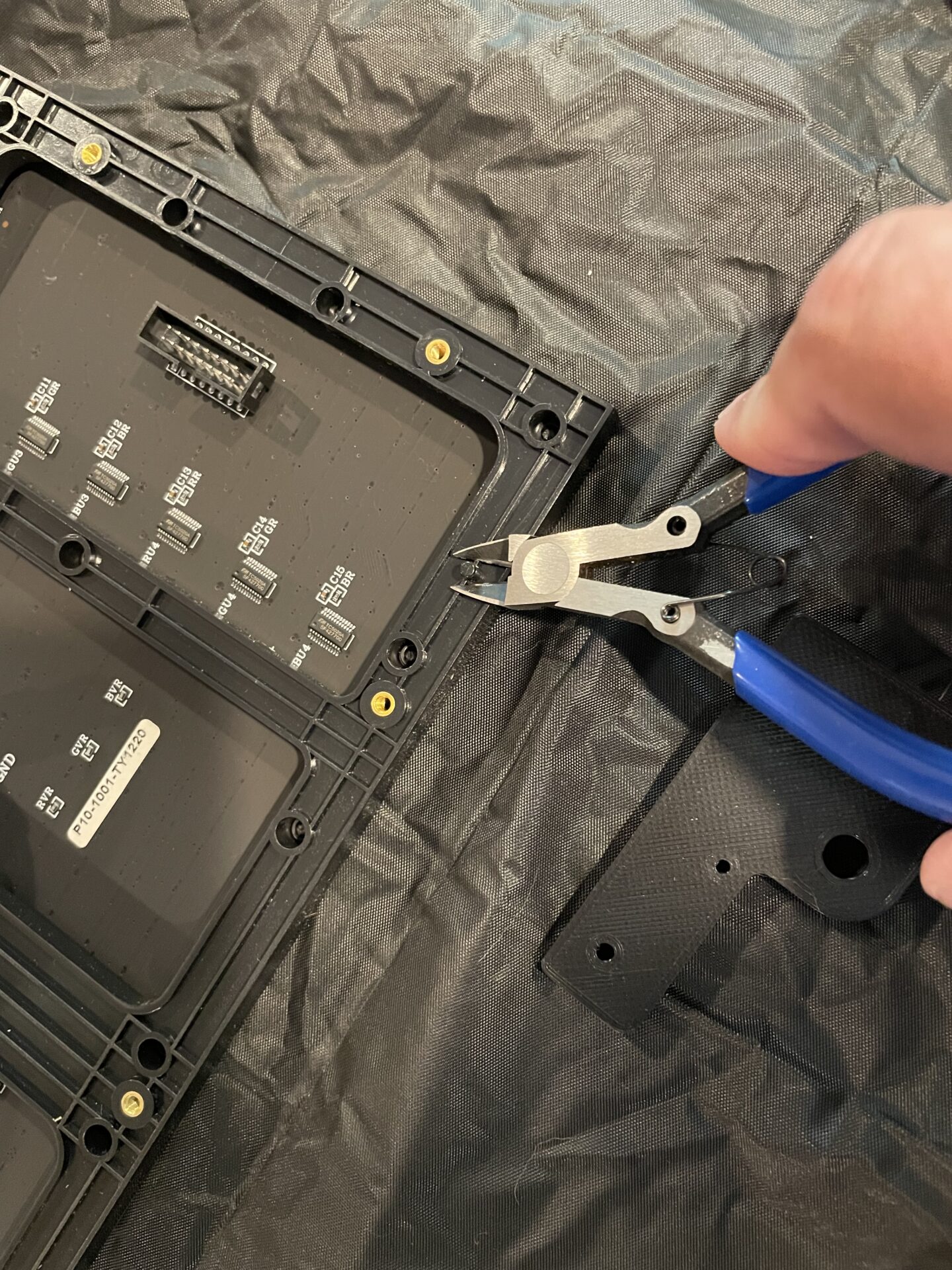
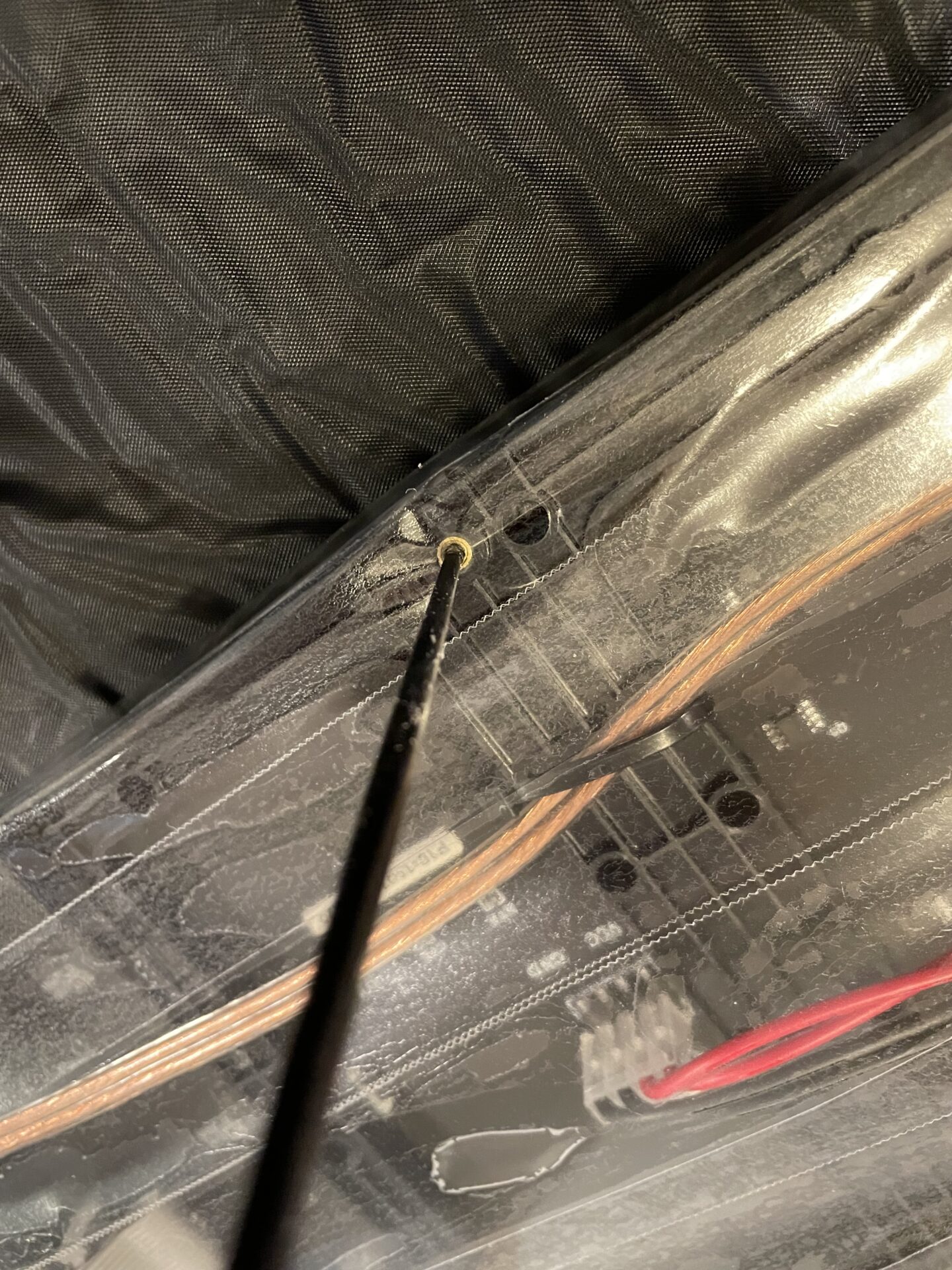
Before I started screwing them together, I had one important thing to do… The panels have locator pins in each corner. I’ve found different manufacturers put them in different places, and the 3D-printed panel connectors themselves don’t have holes in the right places for these. I just snip them all off with a pair of side-cutters:
Next, I just screwed them all together using 2mmx10mm stainless steel screws. You really want a good drill-driver or electric screwdriver for this- there are a LOT of screws.
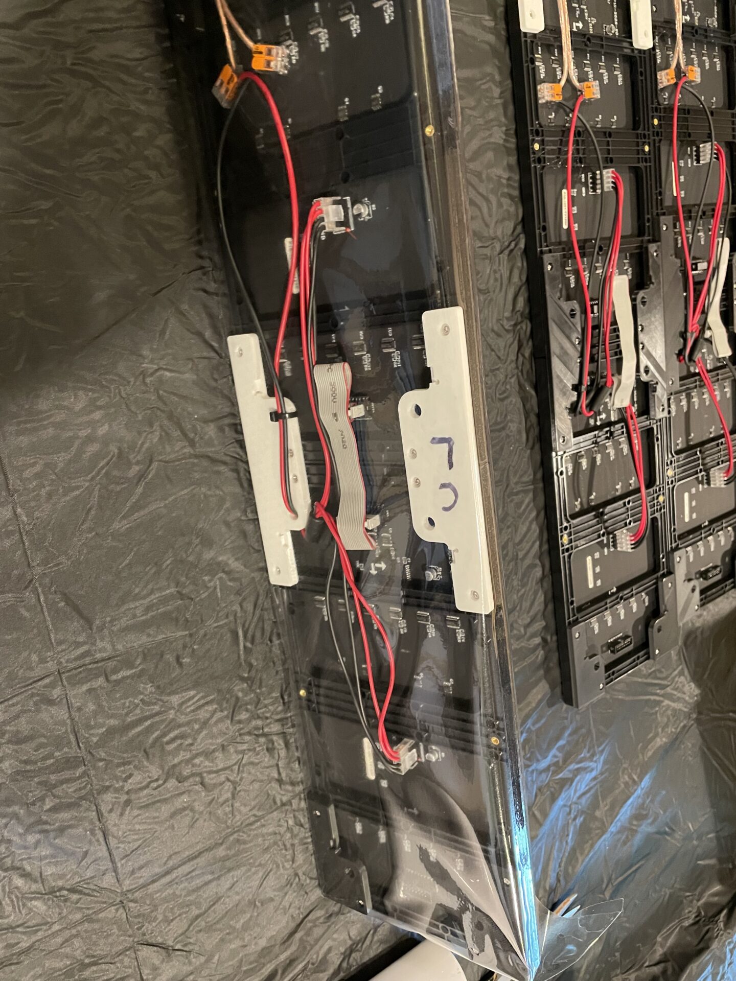
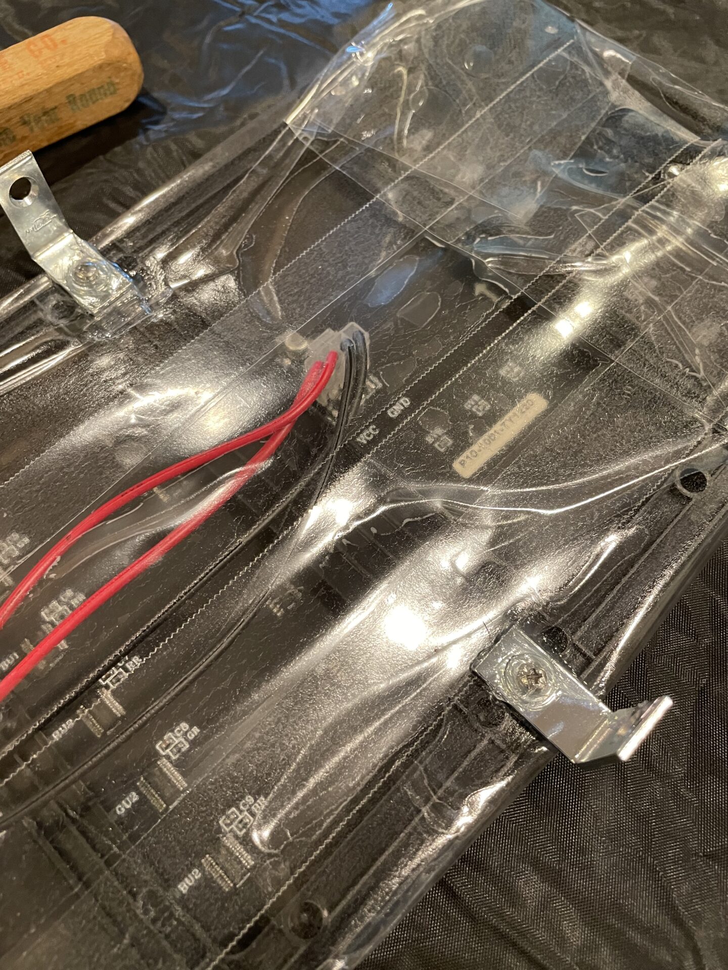
After getting the panels connected together physically, I started wiring up the power and routing the wires where I wanted them. I zip-tied the power wires securely in each section, using the holes provided on the 3D-printed panel connectors.
(For these pictures- I’m building two columns at a time, after building the 1st one as a “prototype”.)
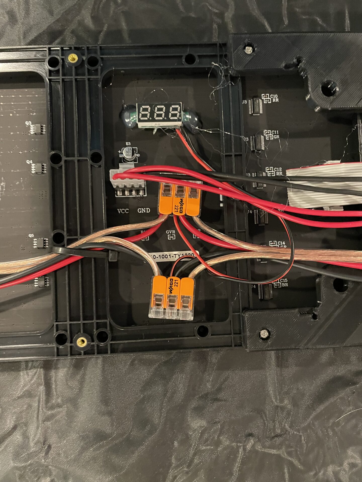
To connect the wires together, I decided to use Wago connectors instead of my usual solder-seals. I did this for two reasons. First- the Wago connectors will make it a lot easier to swap out or add panels or additional wiring components later if I need to. Second, and most-importantly, I RAN OUT of the size of solder-seal connectors I would have needed to complete the project.
I put a dab of hot-melt glue on the bottom of the Wago connectors and tacked them to the panels to keep things neat. Note too- I added a small voltmeter where the first connection is. I add these to all of my builds/props now as it helps me make sure everything is getting the right voltage when I am diagnosing problems. A bit of hot-melt is all that’s needed to “install” it.
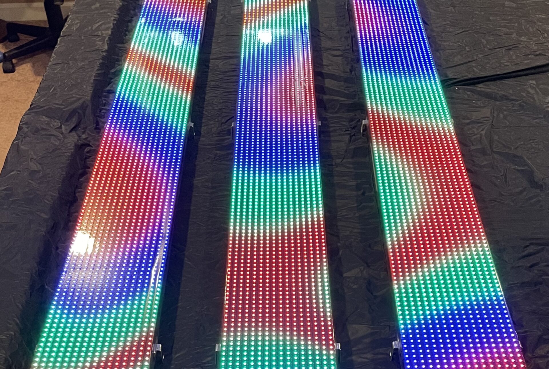
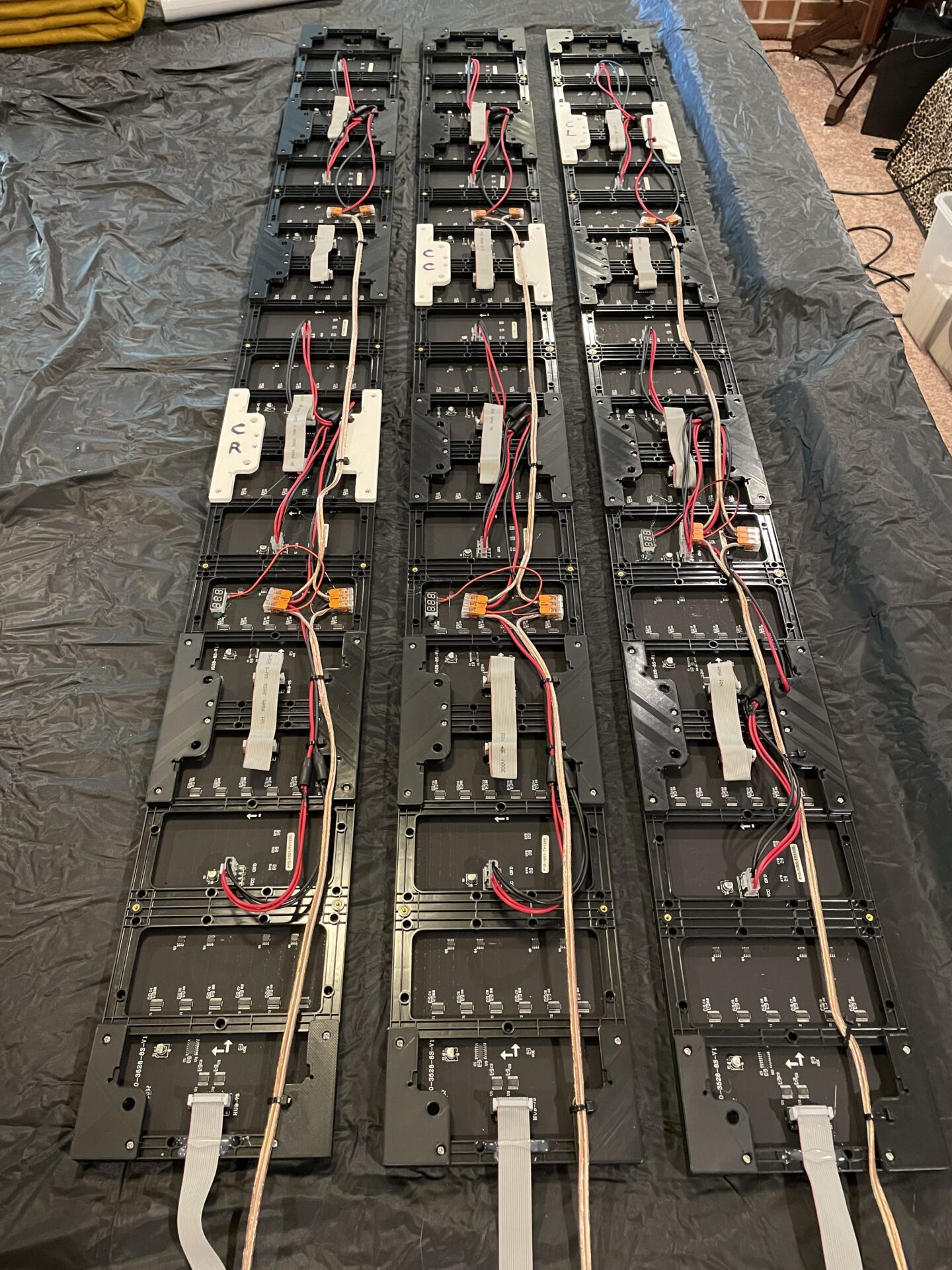
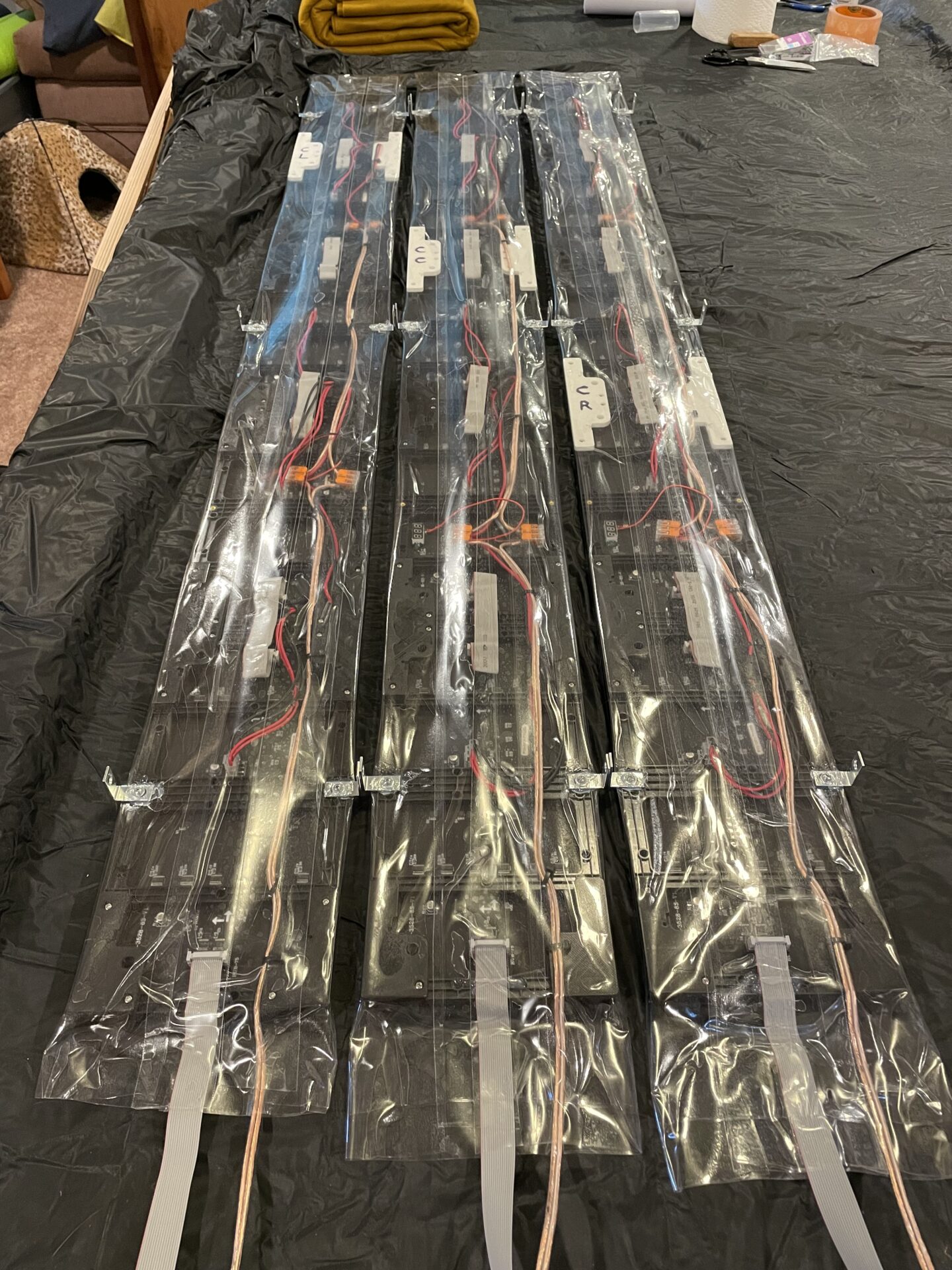
Here are the three completed assemblies. Note the one on the right is the first/prototype one I built, so the wiring is slightly different than the other two.
So, at this point- I have panels assembled. Now what? I need to be able to mount them to the outdoor columns, and protect them from the elements. I don’t want a heavy enclosure made of wood and plexiglass, which is the “normal” way of building these. So…
I turned to the same wonderful material that I used to protect my Info Matrix- self-adhesive sign vinyl! It’s UV rated and made for outdoor use, and it’s thick enough to provide a solid layer of protection for whatever is behind it. It’s easy to use, and fairly inexpensive. Here is a link to the stuff I’ve been buying (affiliate link):
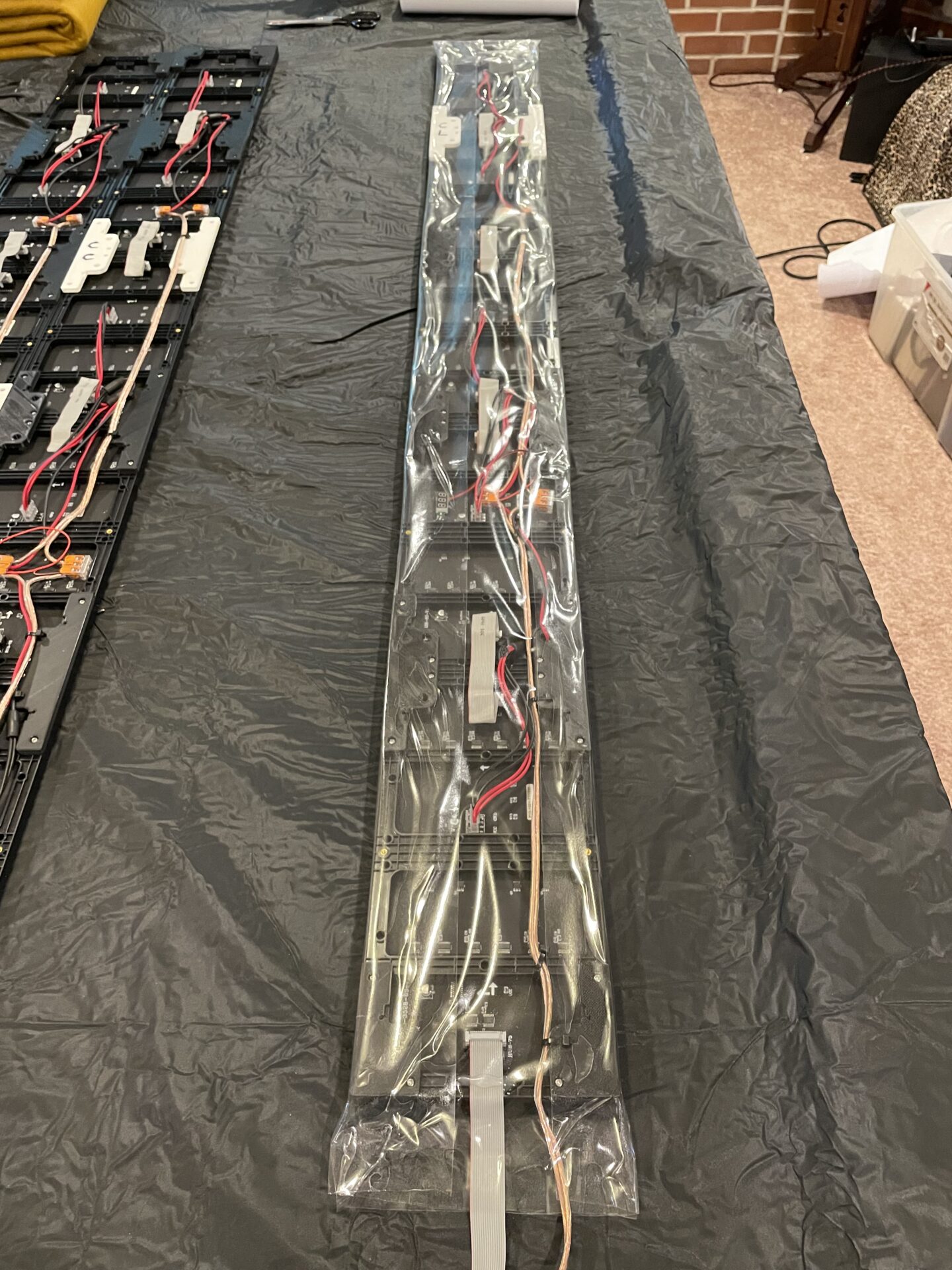
I need to encapsulate the whole thing in vinyl, but keep the front clear. I decided the best way to do this was to first wrap vinyl around the back, cut it even with the face, and then wrap it around the front. This overlaps everything on the edges, and provides a lot of extra material on the back to seal things up. Here is what that process looked like:

I rolled out enough film to go a few inches past the top and bottom of the panel, and removed the protective paper from the adhesive. Then, I set the panel in the middle and simply rolled it to each side to adhere the film to the sides. Then, after pressing it to make sure it was well adhered, I trimmed off the excess on the front. This enclosed the back of the panel in vinyl.
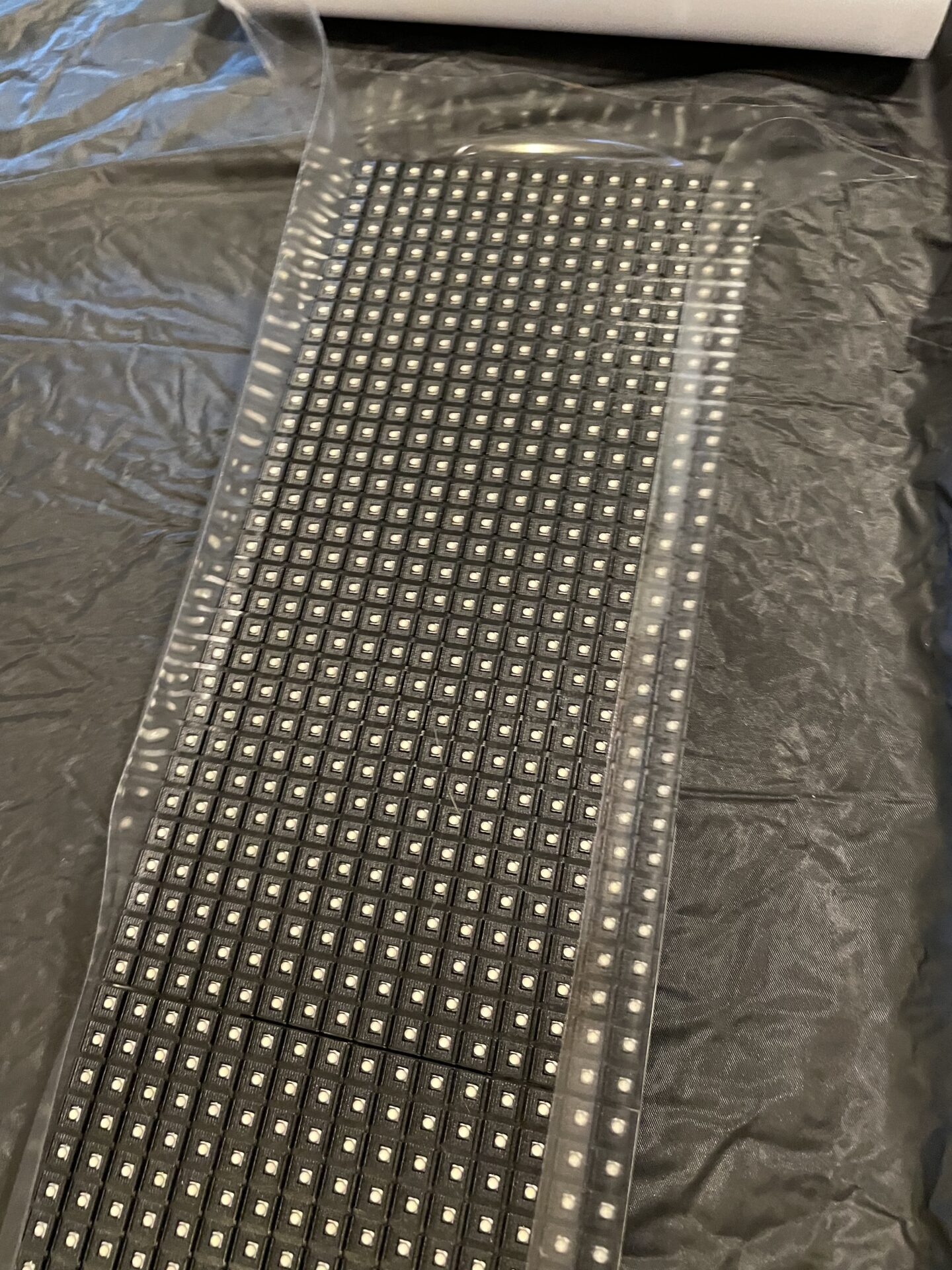
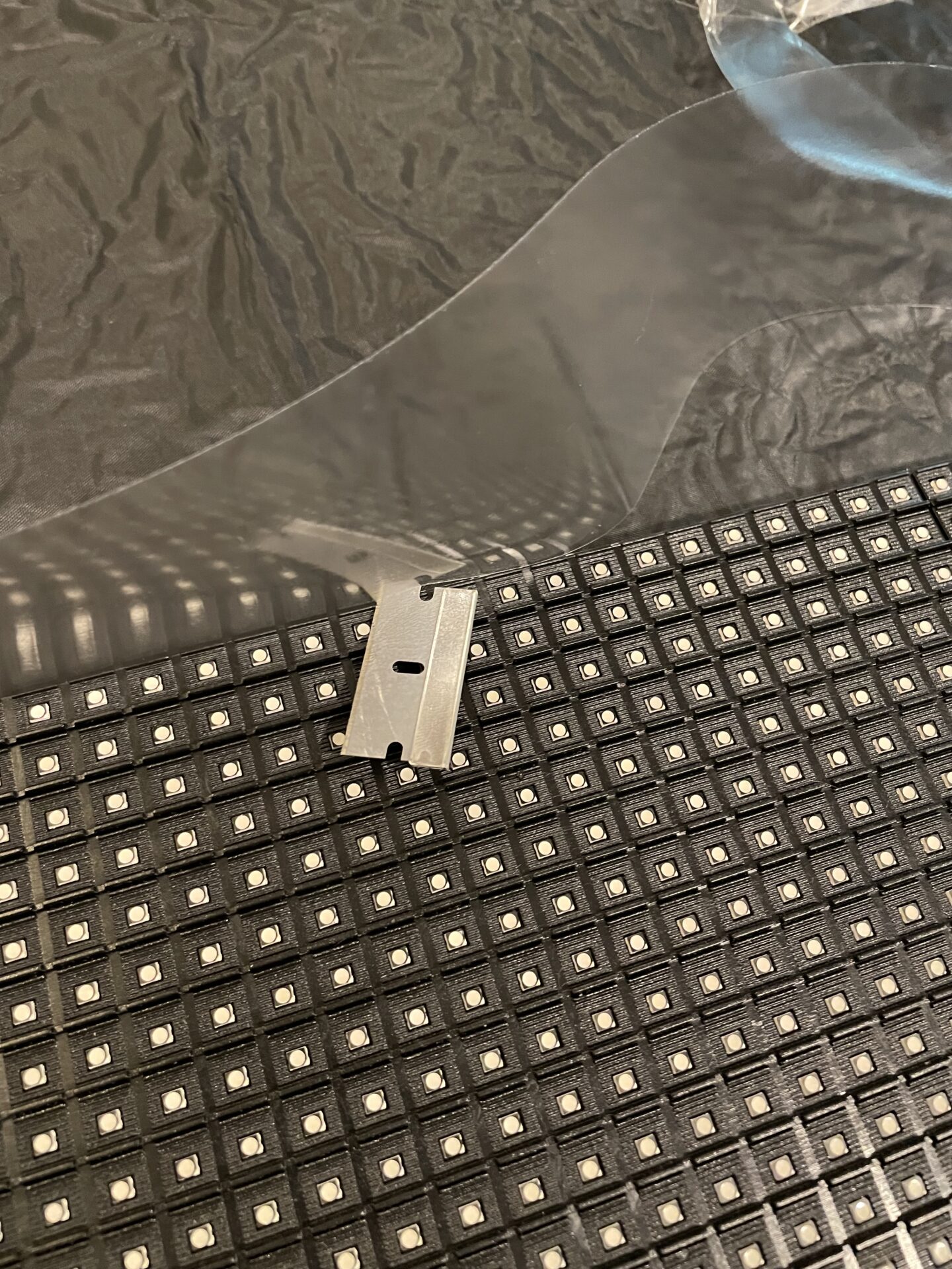
It actually went easier than I thought. Rolling the panel side-to-side made it easy to adhere the vinyl evenly. I only had a couple of odd creases, but they were covered up by the next step- covering the front…
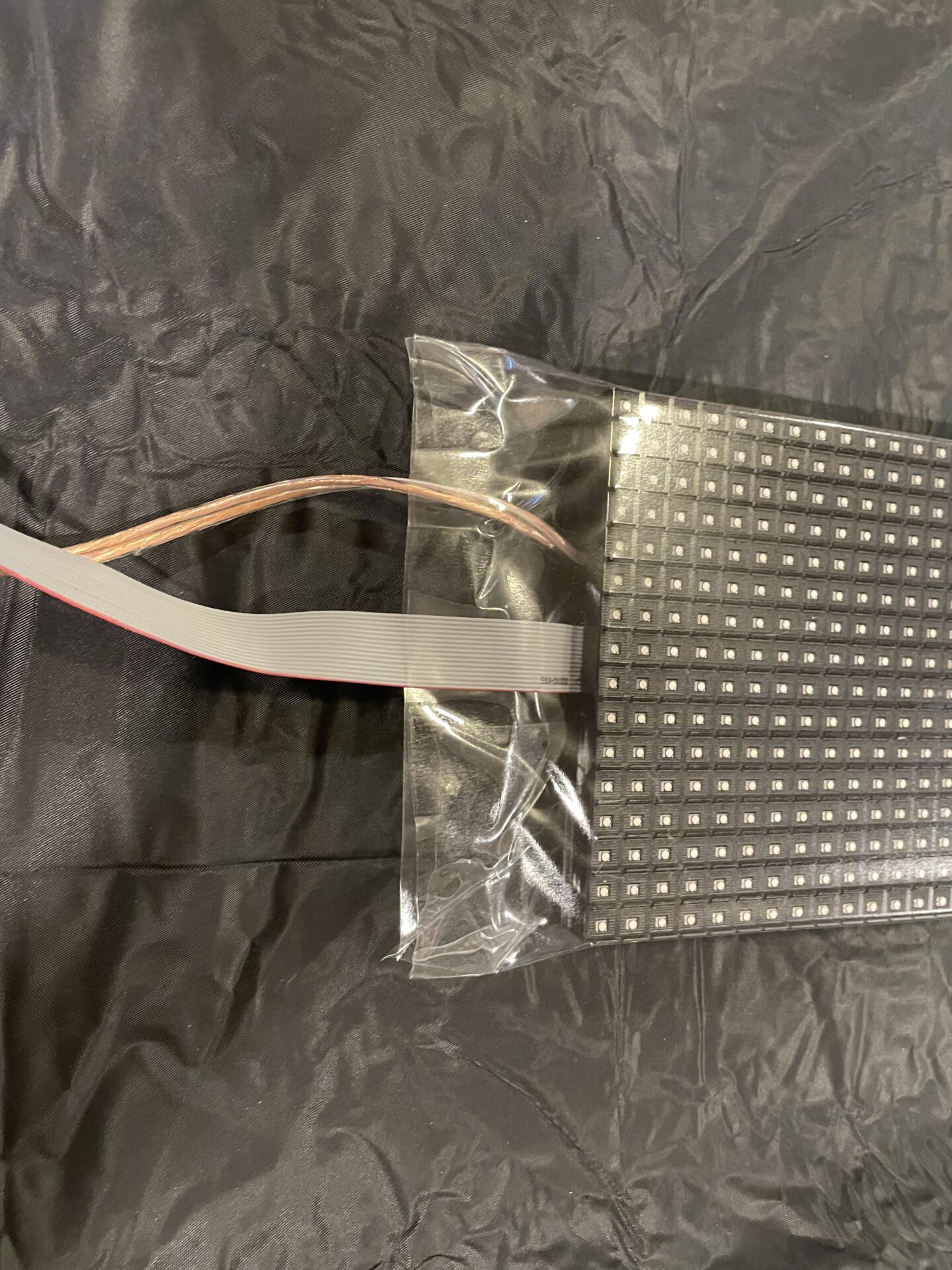
I rolled out enough film to go a few inches past the top and bottom of the panel, and removed the protective paper from the adhesive. The same as the back- after setting the panel in the middle of the film, I rolled it from side to side to evenly wrap the vinyl around the edges. Unlike the front- I kept the extra film and adhered it around the back film. I stuck both sides together at the top, and folded them down, sort of like gift wrapping. The top is well sealed, but for a bit of extra security I used clear Gorilla Tape to seal all of the edges. The bottom is just adhered to itself, around the power and data cables. There are some creases and spaces around the wires that should allow any water that sneaks in to drain out the bottom. This also allows some air in and out.
Is it perfect? Nope- there are some wrinkles here and there, and I didn’t get the film as tight as I would have liked on the front, but it doesn’t really matter. At night- you won’t be able to see the plastic anyway- just the LEDs. During the day- they are seen from about 100′ away anyhow. The goal though was to seal the panels in an envelope of plastic, and I feel that was accomplished quite handily in this case.
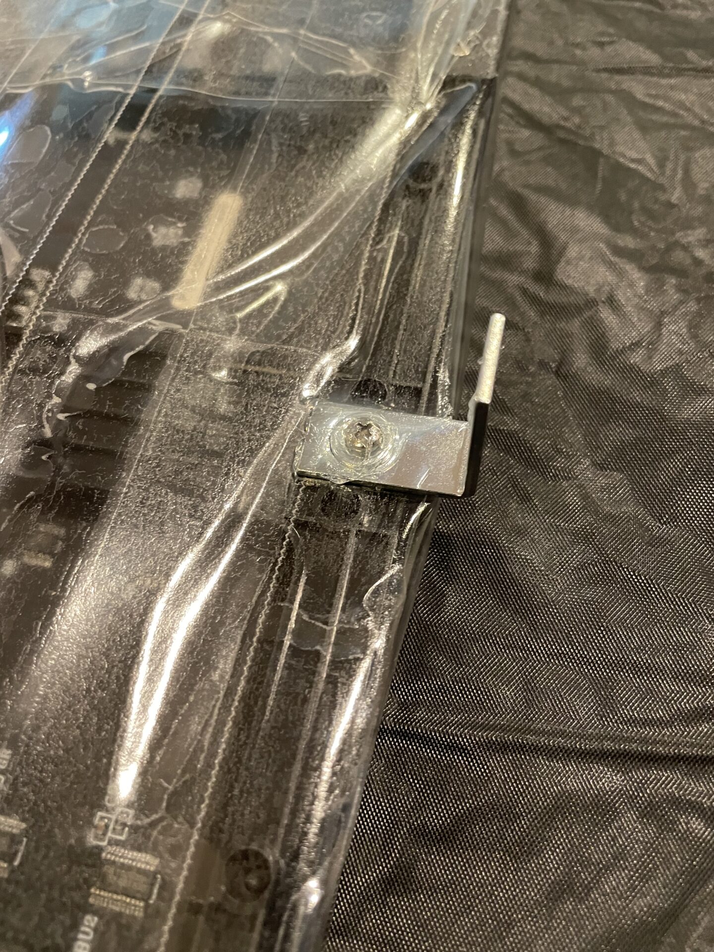
So, one last step for the physical build. I need a way to hang these up by tying them to the columns. The cheap and easy solution is just to use little “corner repair” angles from a hardware store. I decided to fasten them to open screw holes in three of the panels (top, middle, and bottom).
I used an ice pick to punch a hole through the plastic where each bracket needs to go. I then used the same stainless steel screws and small washers to secure them. I used silicone sealant underneath and on top of them. Detail. I used a lot of sealant underneath (before I tightened the screw) and on top of the bracket to keep water out.
Now, I can just hang them up with zip-ties wrapped around the columns.
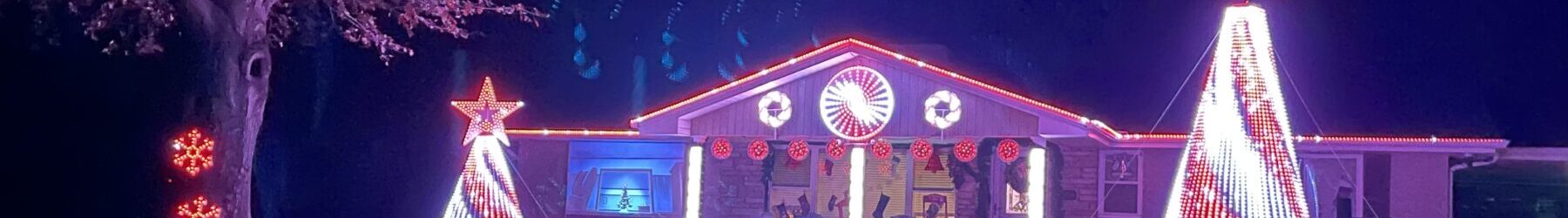
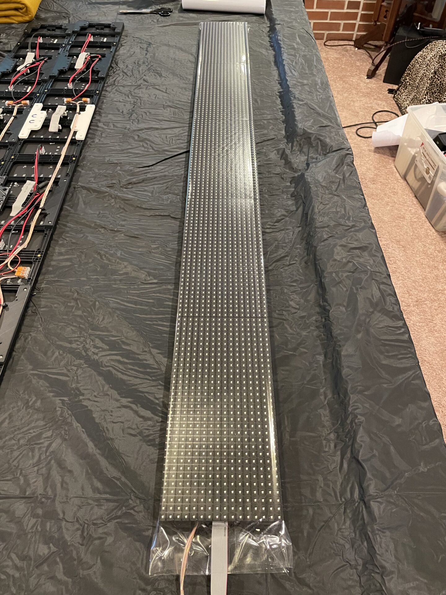
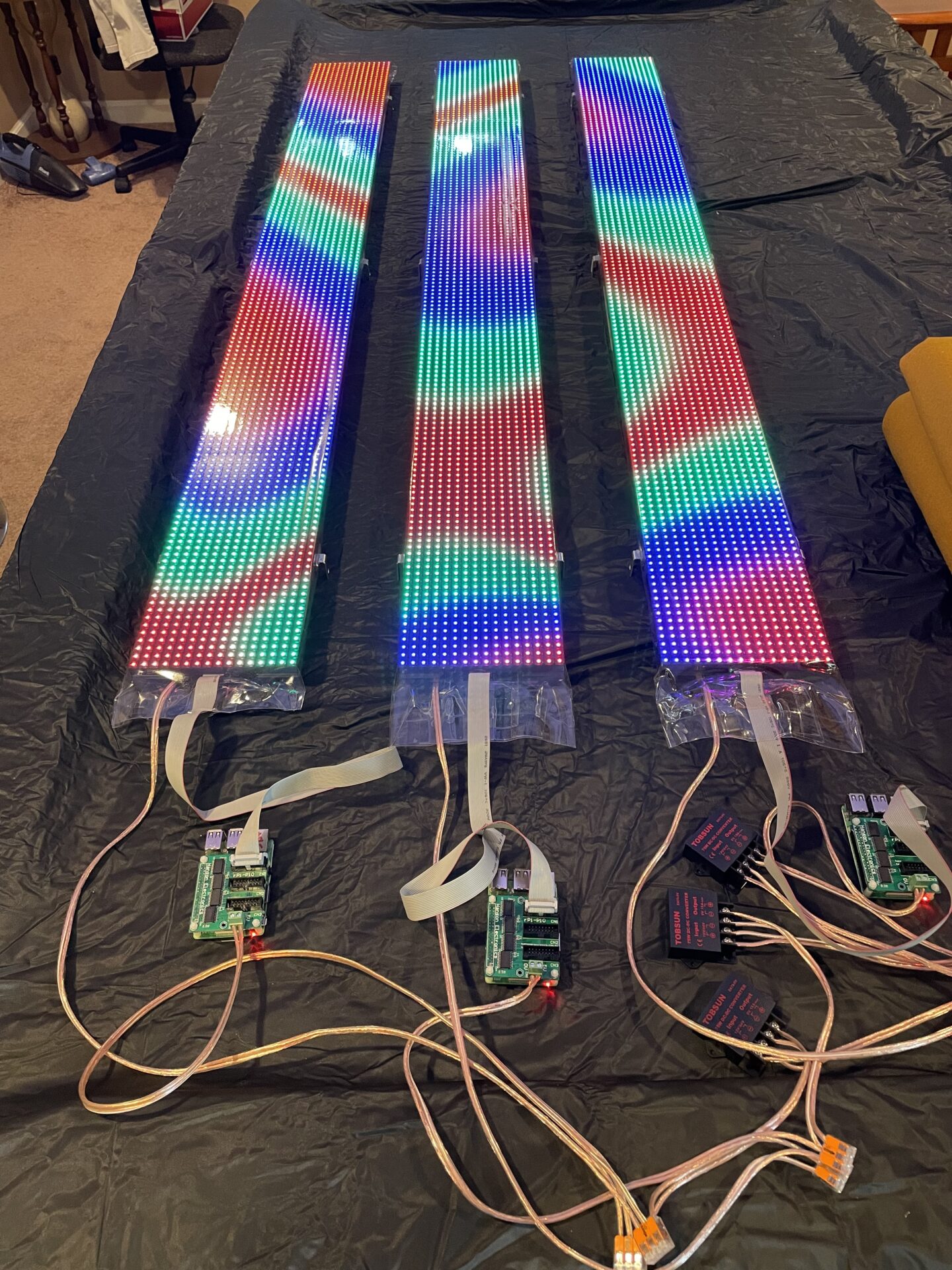
Here are the completed column matrixes:
Now, let’s talk controllers, because this has been a problem for me…
Remember I said “cheap” as one of my goals? Well- the cheapest stand-alone panel controller I could come up with was to use a Raspberry Pi with a Pi-P10 Cap from Hanson Electronics:
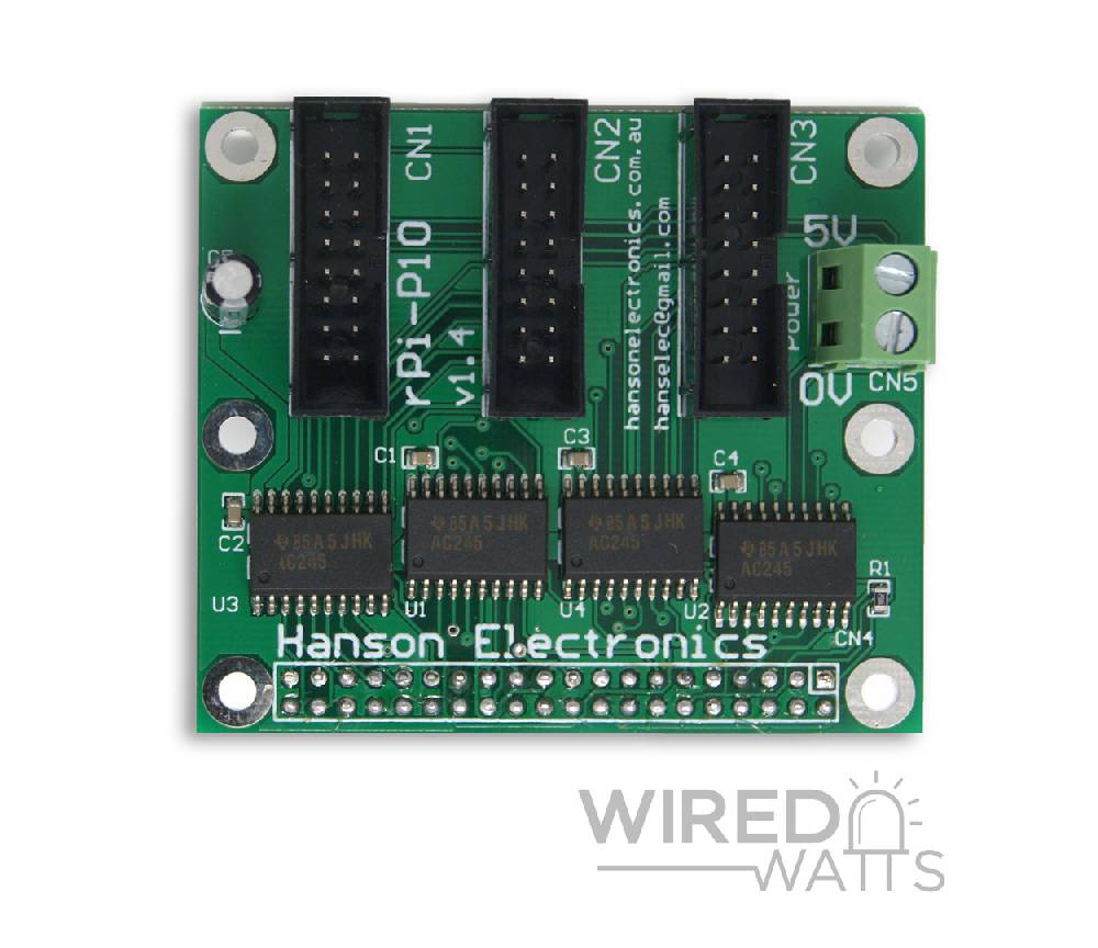
I already had some Raspberry Pis, so this was a $20 each solution for panel controllers. Can’t get much cheaper than that. I plugged them in to three Raspberry Pis, loaded up FPP on them, and was ready to go! Except…
I can’t get it to work well. I don’t know if it’s the controller boards themselves, the Raspberry Pi 3B+ SBCs that I’m using, the panels, FPP, or a combination of all of them. I can get them to display what I want, but they flicker, sometimes badly. There are warnings in FPP against using RPi-based controllers because they are very limited. I also found a note on Hanson’s site about setting the “GPIO Slowdown” option in FPP. Regardless of what slowdown settings I choose- the panels still flicker.
I ruled out power, both by verifying it using the little voltmeters I have attached to the matrixes, and by using three different power supply options, all with more-than-adequate amps to drive the panels. I also put the RPi/Controllers on their own PSUs to further isolate the problem. It’s definitely some kind of an incompatibility between them or FPP and the panels. It’s happening on ALL THREE too.
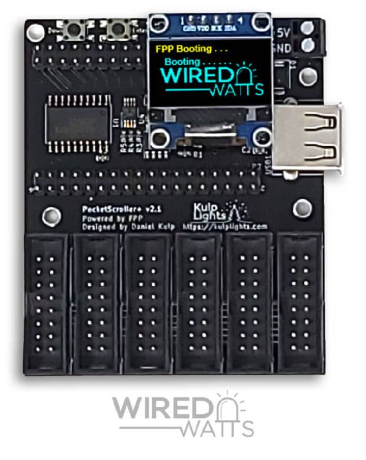
I had a spare Kulp Pocket Scroller I bought as a backup for the Info Matrix. I hooked it up to each of the three matrixes and presto- no flickering at all.
I reached out for support on the FPP Support Group on Facebook and was simply told they “don’t work well” and the FPP devs recommend using something else. That kinda sucks. I reached out to Wired Watts via FB for any suggestions and did not hear back from Ken (which is really unusual).
So now, I’m faced with buying three more Pocket Scrollers, which is a less expensive option than some of the others, but still not what I wanted to do. There is another option though that I am trying first- Colorlight cards. These are popular and reasonably cheap ($26 each), and will work with the Raspberry Pis I already have set up with FPP (and in xLights), they are just kind-of a pain in the butt to configure from what I have found.
So- stay tuned for more info as I continue to work with P10 panels/controllers. If anyone knows of any hacks/tweaks to get the Pi-P10 caps to actually work- please let me know on social media. I’m hoping there is some obscure Raspberry Pi timing setting that isn’t surfaced in FPP that might fix them.
UPDATE:
I built new controller boxes using Colorlight cards a week later. These worked better, but still not perfect. ☹️
Update (Oct. 2021):
Unfortunately the Colorlight cards didn’t work either. The produced randomly flashing lines which I was unable to get rid of, even stepping through dozens of different configuration suggestions I found online. Apparently these “new” panels use (cheap) timing chips that they just can’t deal with, especially anything Raspberry Pi based. So- I ended up buying three more relatively-expensive PocketScrollers. I’m only going to recommend them moving forward- they are worth the extra cost, and drive these “new” and “old” panels perfectly!
My personal recommendation at this point is- if you are new to panels- just buy a PocketScroller. Odds are any of the Raspberry Pi based options won’t work, although maybe it’s an issue with FPP that will eventually get fixed, or someone will come up with and post the magic Colorlight configuration that actually works. In the meantime- save yourself a LOT of time and frustration.
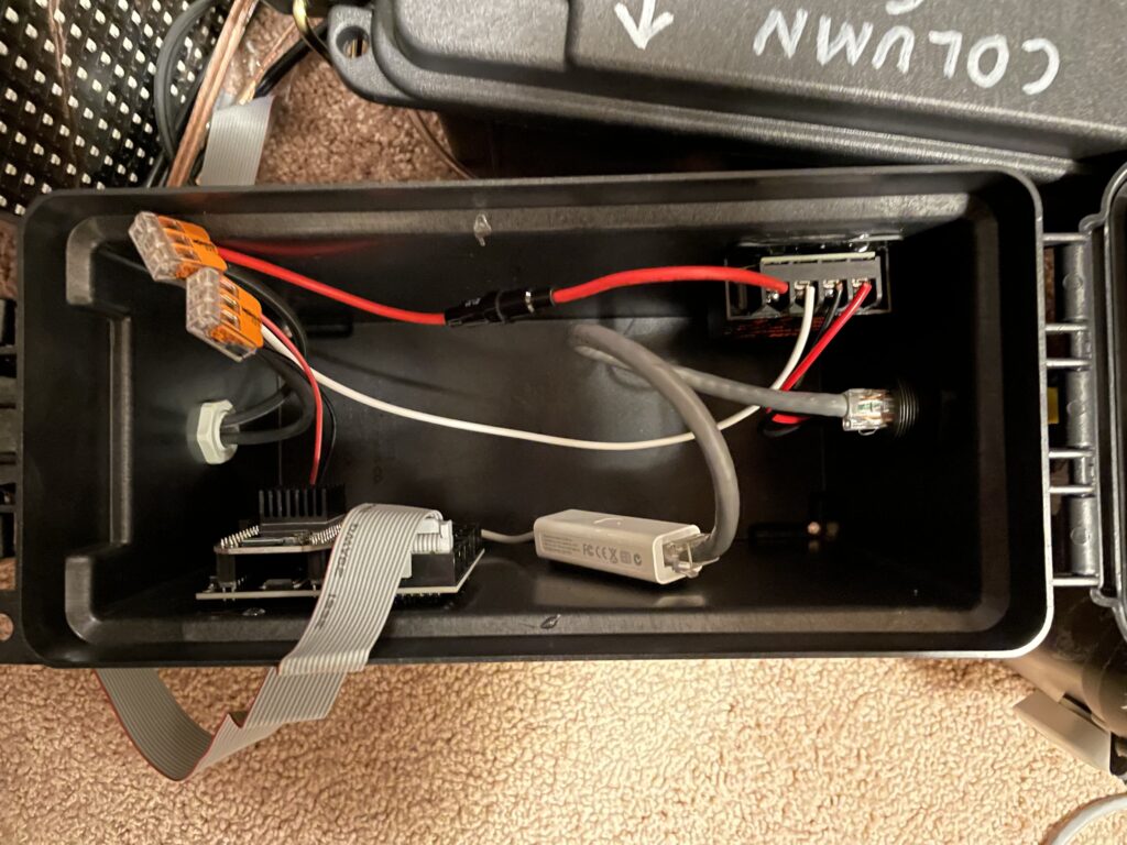
So- I pulled the Raspberry Pis and Colorlight cards out of their ammo boxes, and installed PocketScrollers in their place. I just used some heavy-duty hook-and-loop to secure them. And- they work perfectly. I did use some old USB Ethernet dongles and have them wired up, instead of buying more WIFI adapters. FYI- if you have any old Mac USB Ethernet adapters lying around- they work just fine. Here is the finished “product”…