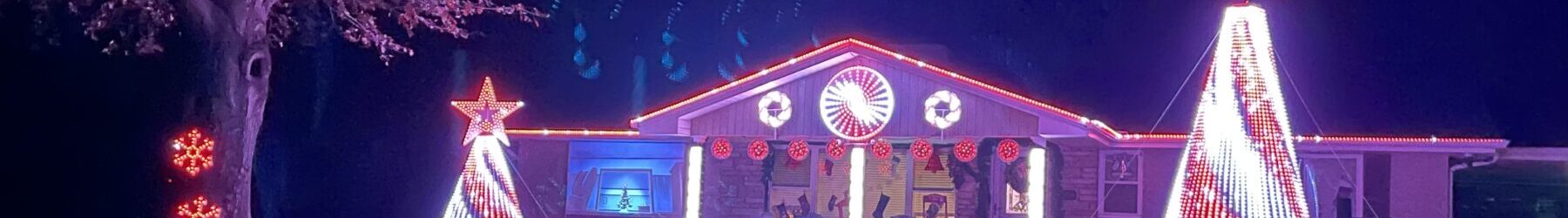
Colorlight Controller Box Builds
Last week I posted about my P10 Column Build. One big problem I had was the Pi-P10 controllers I tried to use just didn’t work. They had a terrible amount of flicker, and I was unable to find any actual support for them. So- my next most expensive option was to switch to Colorlight cards.
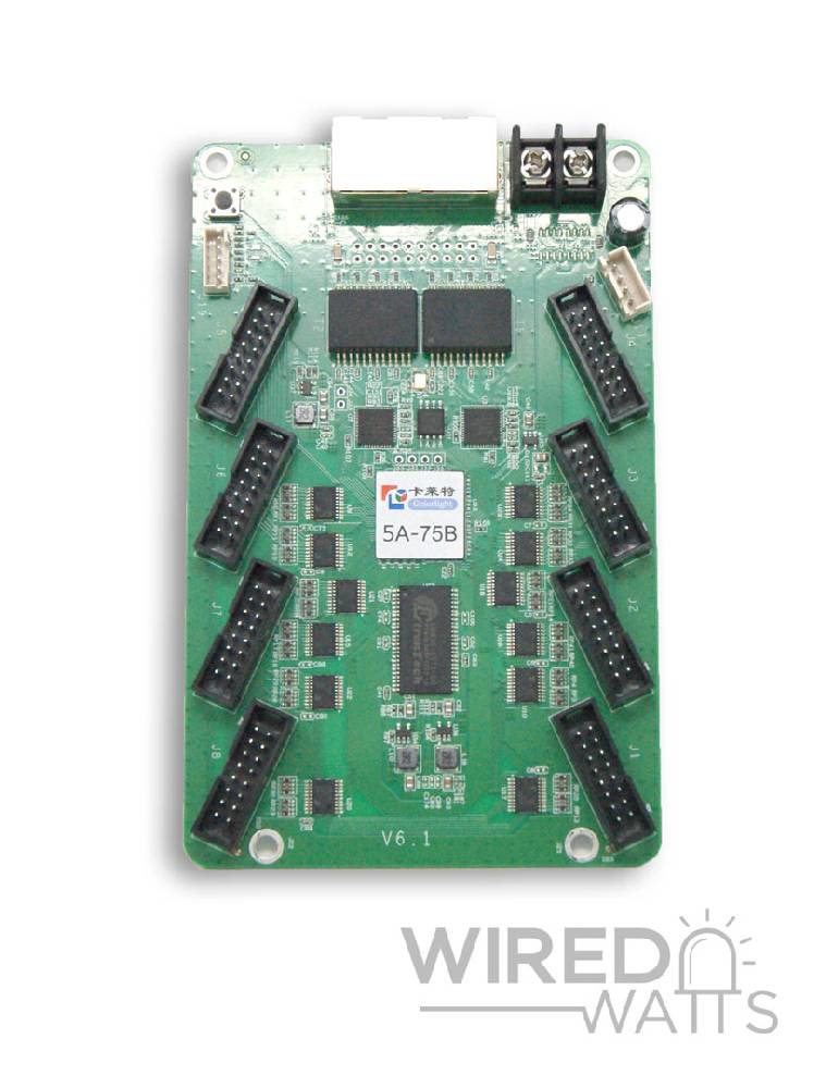
These are purpose-built cards made specifically to drive portions of very-large P10 or similar LED displays. They are reasonably inexpensive (around $26 as of this post), and while they are a bit of a pain to configure- once configured they should “just work”. One oddity with them is they need to be connected to a control computer (or a “Sender Card”) using Gigabit Ethernet, although once initially configured- they use their own proprietary networking protocol. It is also possible to daisy-chain (up to 3 with FPP) multiple cards together, which is what they have two RJ-45 ports.
Since I am replacing bad Pi-P10 controllers and already have three Raspberry Pis for my three column arrays, I decided to just hook each one up stand-alone, and not try to mess with daisy chaining.
Configuring the cards is a bit hit-and-miss and requires special software from a Chinese supplier, running in Windows. It took me several tries to get the right combination that (sort of, see below) works with my panels. I’m not going to go into detail since there are a lot of other how-to resources and too many variables between panel manufacturers and matrix configurations. Here are some links to help with configuring:
https://www.wiredwatts.com/colorlight-setup-for-outdoor-p5-panels
You can use the same process for P10 panels, just remember they are 16px high by 32px wide, and obviously pick P10 options instead of P5.
One more video that covers the whole process:
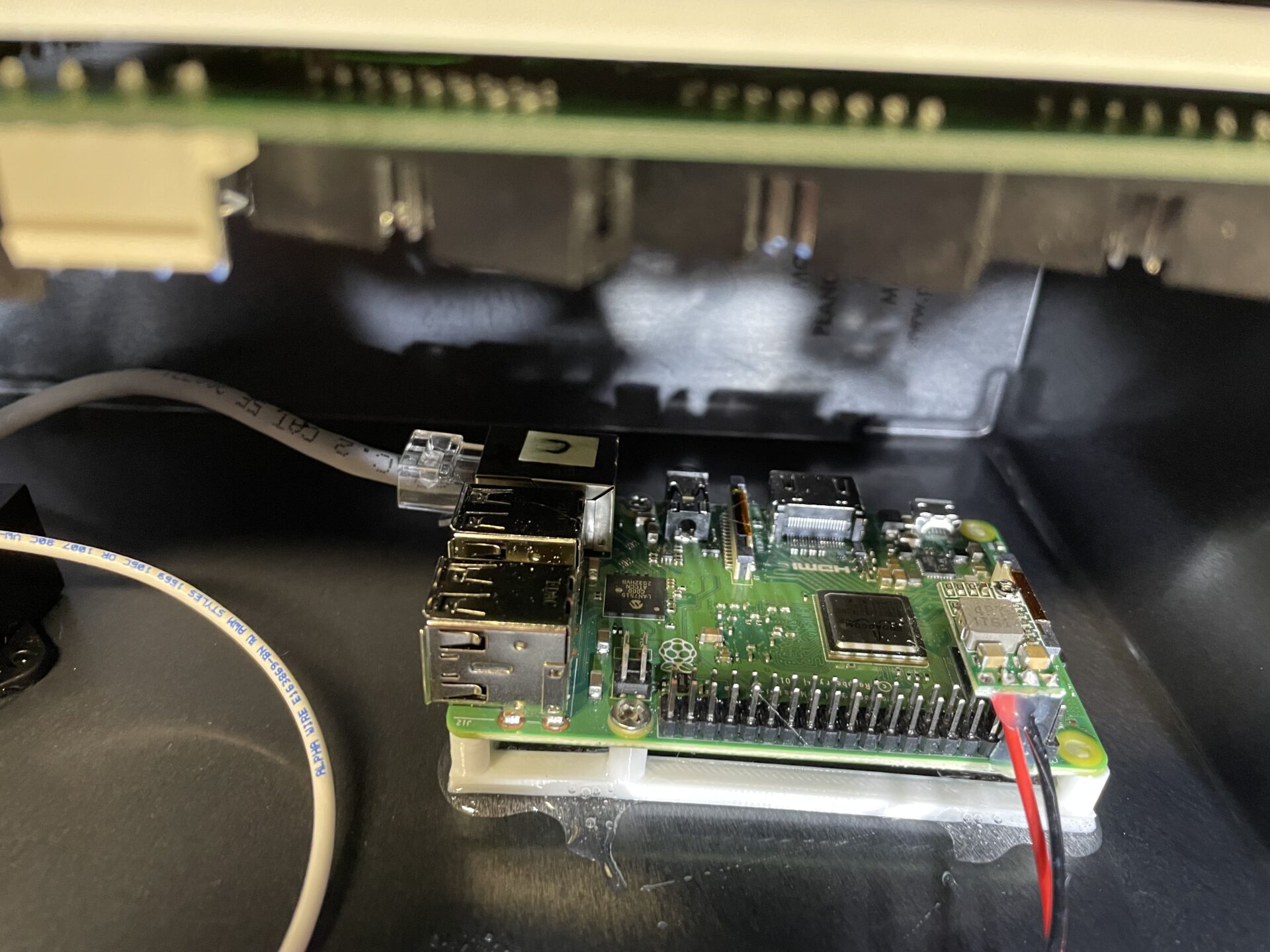
The Raspberry Pis 3B+ SBCs I’m using to drive the Colorlight cards are running FPP v.5. I’m connecting them directly to the Colorlight cards using short Ethernet Crossover cables (see below). Since they have gigabit Ethernet ports- they work just fine with the Colorlights. I have the Ethernet ports configured with a dummy IP address, 10.11.12.13/255.255.255.0 so it can “talk” to the Colorlight card. They are all the same, as they aren’t connecting to a larger wired network. I’m running them in Remote mode and they are connected to a new dedicated WiFi network I built for the show using their internal WiFi. IF I have WiFi problems this year, I already have USB to Ethernet adapters for them, and can connect them to the wired show network quickly. After last year’s WiFi issues, I’m trying to be ready, but I’m not buying all that expensive (these days) Ethernet cable if I don’t have to. 🙂
As usual, I wanted the cheapest option for an enclosure for each “controller”, so I’m. using the good-old standby: Plastic Ammo Boxes


I buy whatever is on-sale from either Harbor Freight or Menards. They both work about the same. I feel Menards are built better and have a higher quality seal. You can usually find one or the other on-sale for around $5.
Each controller box needs the following:
Colorlight Card
Raspberry Pi
Buck Converter (for Power) *
*The link explains this. I’m using a 12v PSU to drive all three columns, with a 15A buck converter to reduce the voltage to 5v for each one. I’ll also note that I regulate the voltage to the Raspberry Pis too.
I could have just used heavy-duty hook-and-loop tape to fasten everything inside, but I decided to use some 3D printed mounts and epoxy instead. I may regret this as one of the Colorlight cards already came loose in one of the boxes, and I need to get more epoxy to fix it.
Here are the mounts that I 3D printed:
Colorlight P10 Mount
Raspberry Pi 3 Mount
I also needed a short “Crossover” network cable to connect the Pi to the Colorlight. I don’t believe this is strictly necessary- as a standard Ethernet cable probably would have worked just as well with this hardware, but usually you use a crossover cable between two Ethernet devices that are not switches or routers. I make most of my own cables anyway, so this was easy. Here is a good write-up about what crossover cables are and how to make them. Basically you are just swapping the green and orange pairs for one of the RJ-45s:
https://www.makeuseof.com/tag/ethernet-crossover-cable/
So, I figured out the best placement for everything, and used quick-set epoxy to affix the components to the sides of the ammo boxes. As usual- I keep everything elevated off the bottom so if any water does get into the box- they won’t be sitting in it. Here is a slide show covering the build:

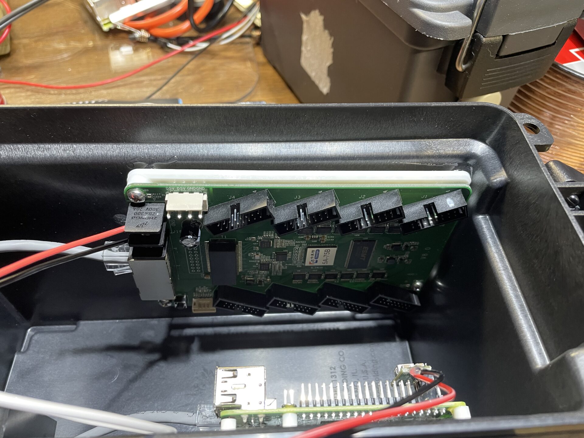
Colorlight card epoxied to one side of the box. Note that Port 1 (marked with a white dot by me) is on TOP. Raspberry Pi epoxied to the opposite side. 12v->5v 15A buck converter epoxied next to the RPi. 
Components in-place. Giving the epoxy 24 hours to set. Wired up and ready to go! Note the 5v output is fused (10A), and I just used Wago connectors to connect everything.
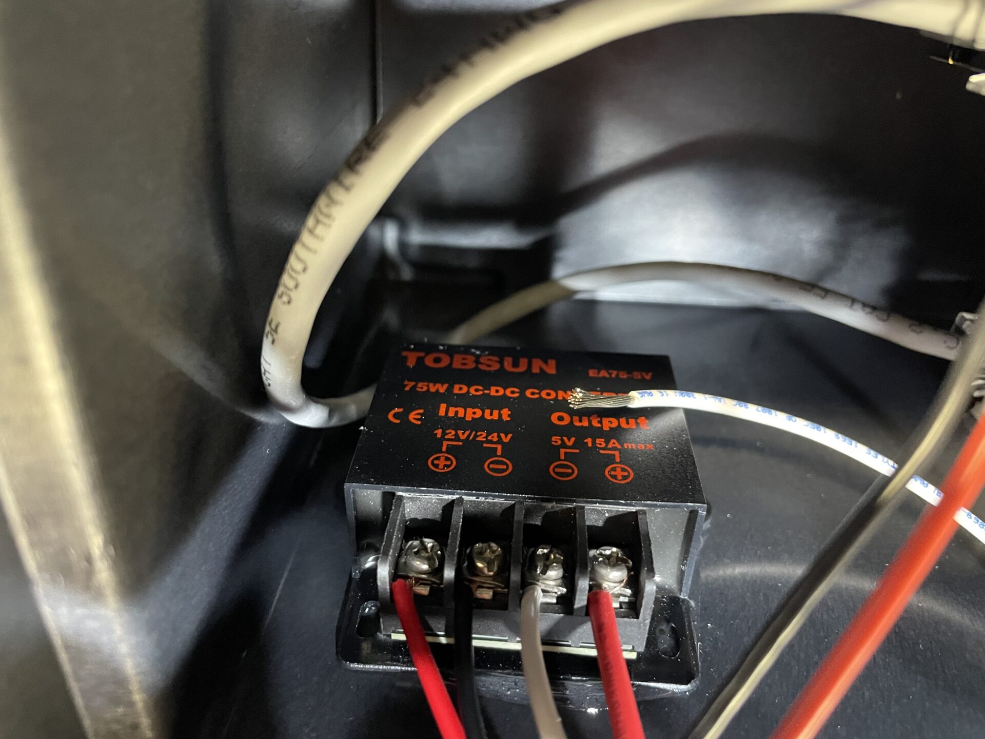
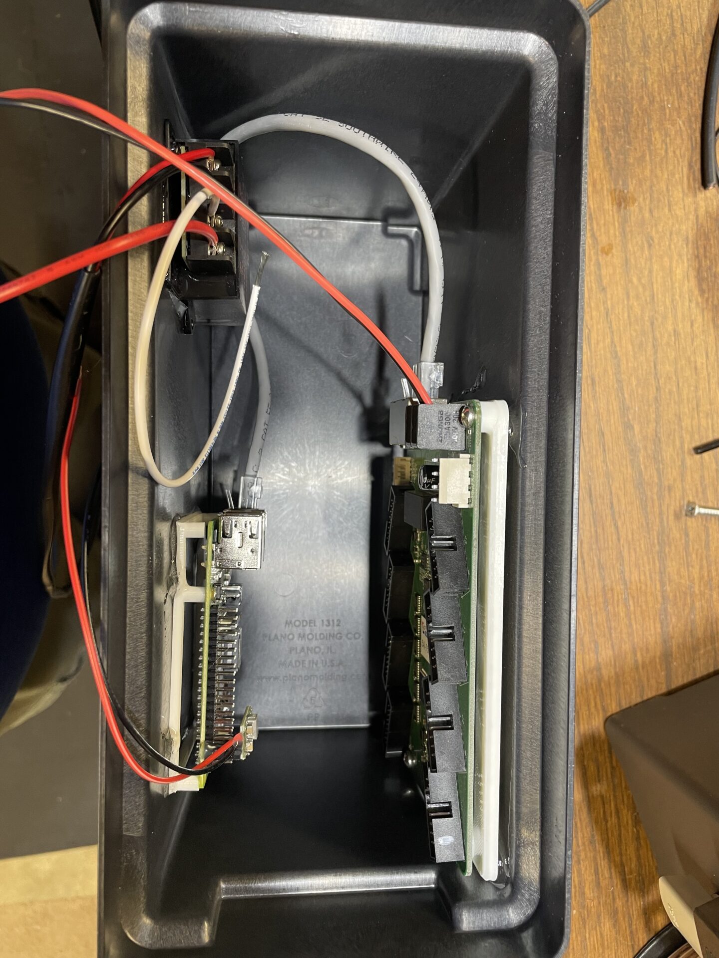
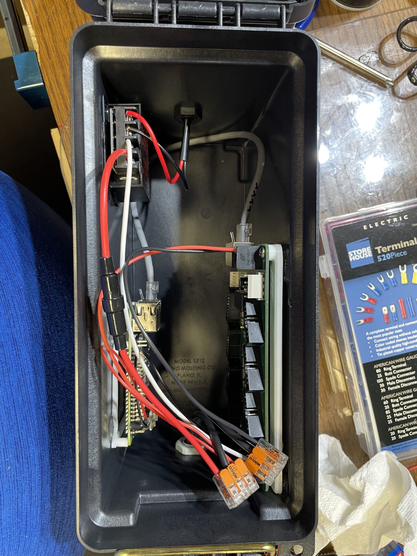
In one end- I’m running 12v power through a cable gland to the buck converter. I’m running 5v from the buck converter to the Colorlight card, Raspberry Pi, and out the other end of the box for the P10 matrix panels. The ribbon cable from Port 1 on the Colorlight card is just fed under the lid, and then out to the panels.
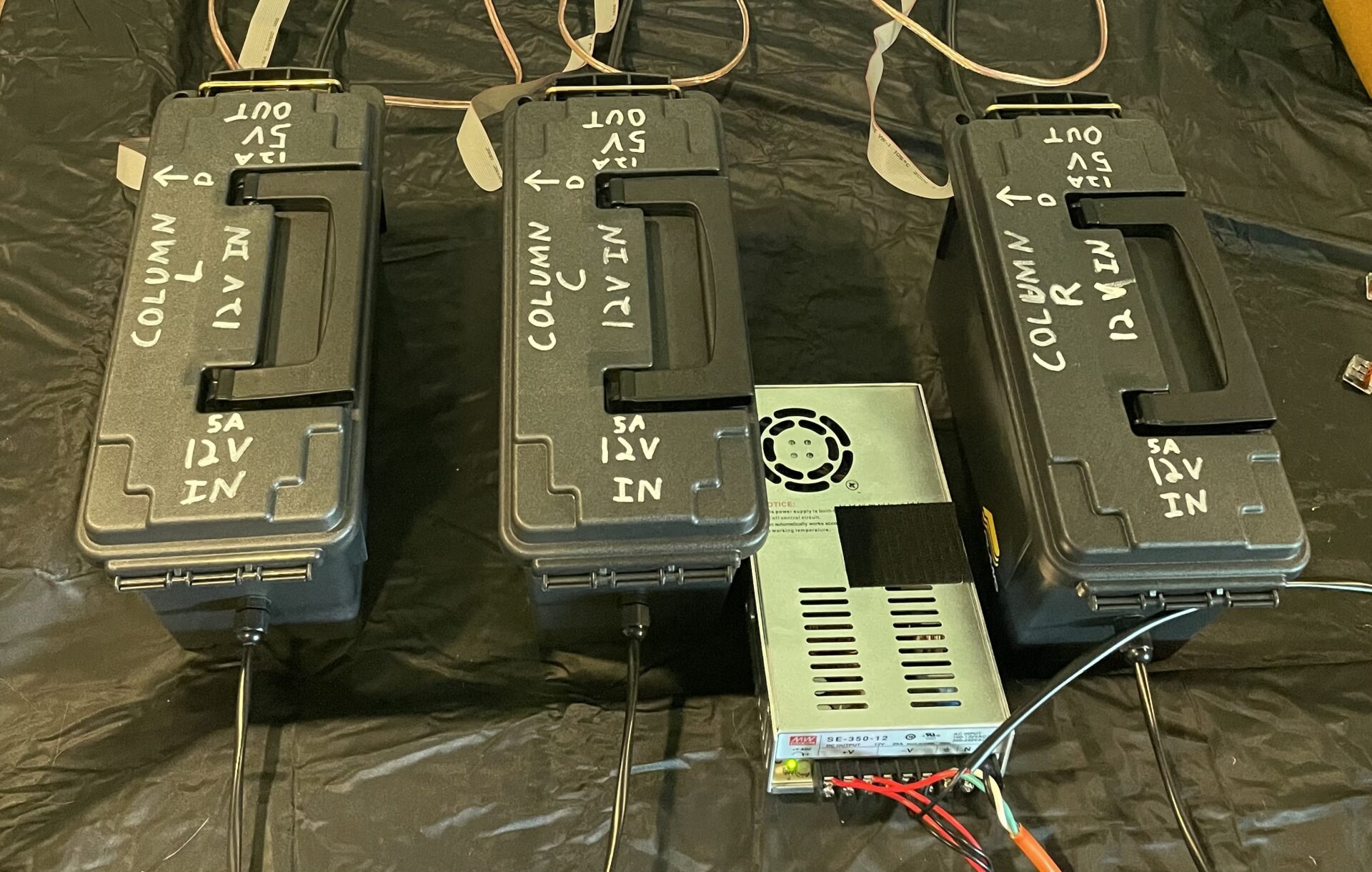
Here is what everything looks like now that it is completed:

I built a “standard” 12v PSU box for the power supply that will run all of this. It just isn’t shown in the above picture. In order to keep everything straight this year- I’m writing detailed info on top of each box to show what it is for and what the inputs and outputs are.
While these boxes will be sheltered on our front porch for the most part, because the ribbon cable breaks the seal of the lid- it’s important to make sure that it dips down for a bit after it exits the lid. That way, any rain or snow the gets on it will drip down, and not follow it into the lid. There is a slight dip anyway because of the way the lid is made, but better safe than sorry. You can’t see them in the pictures above, but as-usual I also have a couple of small drain holes in the bottom of each box, so if water does get in- it will drain out.
I have a new dedicated WiFi network for the show this year, and I’m hoping these will work just fine via WiFi. The Raspberry Pi 3B+ boards that I uses have onboard WiFi. So far they have worked very-well in testing running FPP in Remote mode. If I do have to use Ethernet- I have USB Ethernet adapters I can plug into the Raspberry Pis, and I can feed network cables to each of the boxes.
Now, earlier I said this whole thing “sort of” works. While the display is significantly better than it was using the Pi-P10 controllers, it is still not perfect. When FPP is running a sequence, the 8th and 16th lines of the first three panels in the chain randomly flash. It’s fast and dim, and is more of an annoyance than anything else, but it’s still there. I’ve tried a bunch of combinations of panel configurations on the Colorlight cards, and nothing seems to fix it. It’s doing it on all three controllers/arrays, so I know it isn’t a one-off issue. It only does it when a sequence is running. If there isn’t anything running- the panels stay completely dark. As before- I’m going to try to get some support fo it. Hopefully someone has seen this before and knows what the fix is. Here is a video that shows it: