
Raspberry Pi 5v Power Regulation
We have a lot of Raspberry Pis that run various elements of our shows, and powering them from “wall warts” in enclosures isn’t always practical, especially since we are already running 5v power everywhere. The problem is- if you power them using the GPIO header, there is absolutely no internal voltage regulation. So- a voltage spike or other anomaly can fry your Pi. Many of us tend to run our PSUs a bit higher than 5v too, in order to compensate a bit for voltage drop.
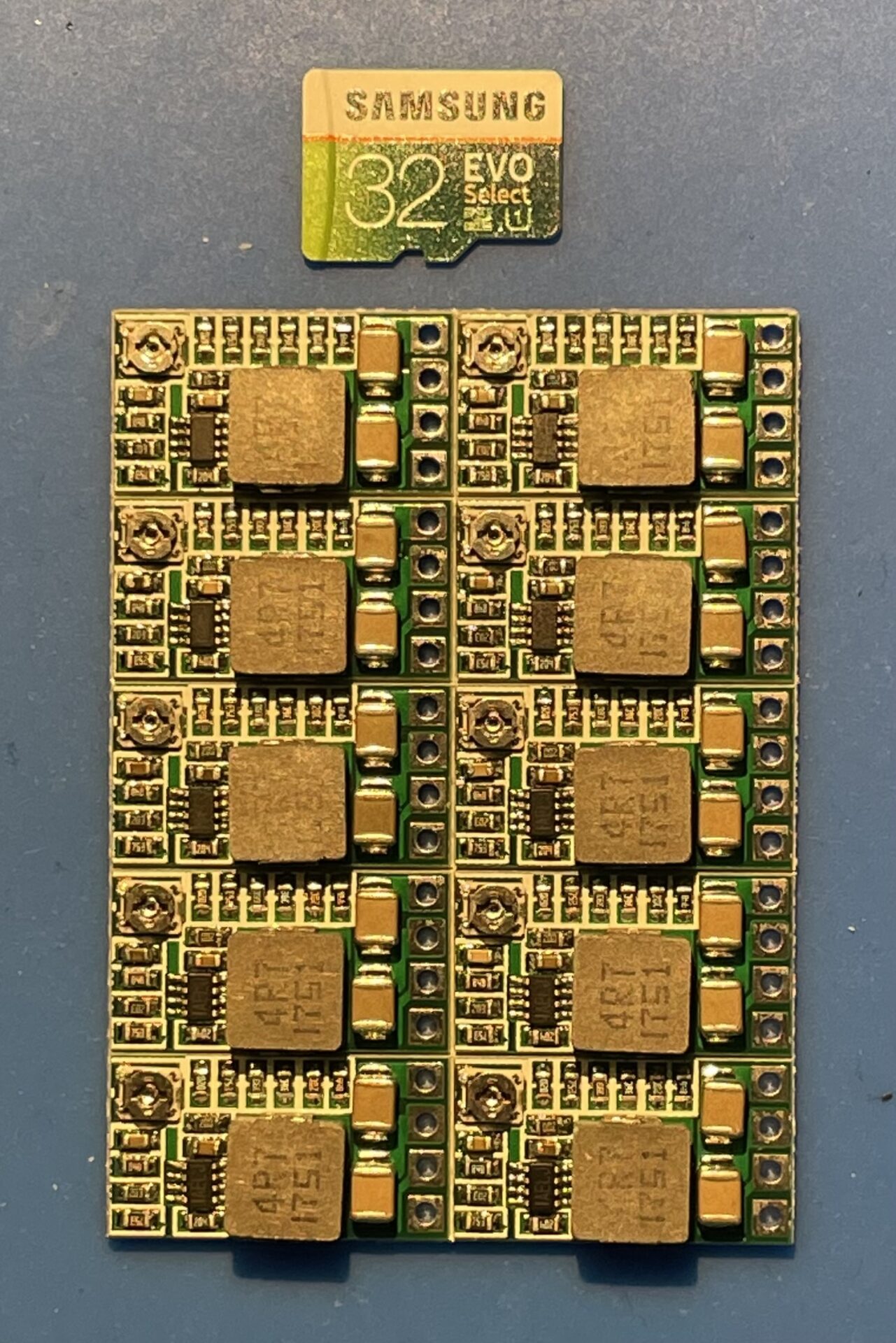
What I decided to do is use cheap buck converters/voltage regulators you can find on Amazon. These can be set to output 5v for any input voltage between 4.5 and 24v:
The are tiny, almost alarmingly so, and working with them at least for me at my age involves using a magnifying glass. They come in blocks of 10- you can just gently break them apart. Fortunately they do have rather large (for their size) solder pads to connect them up.
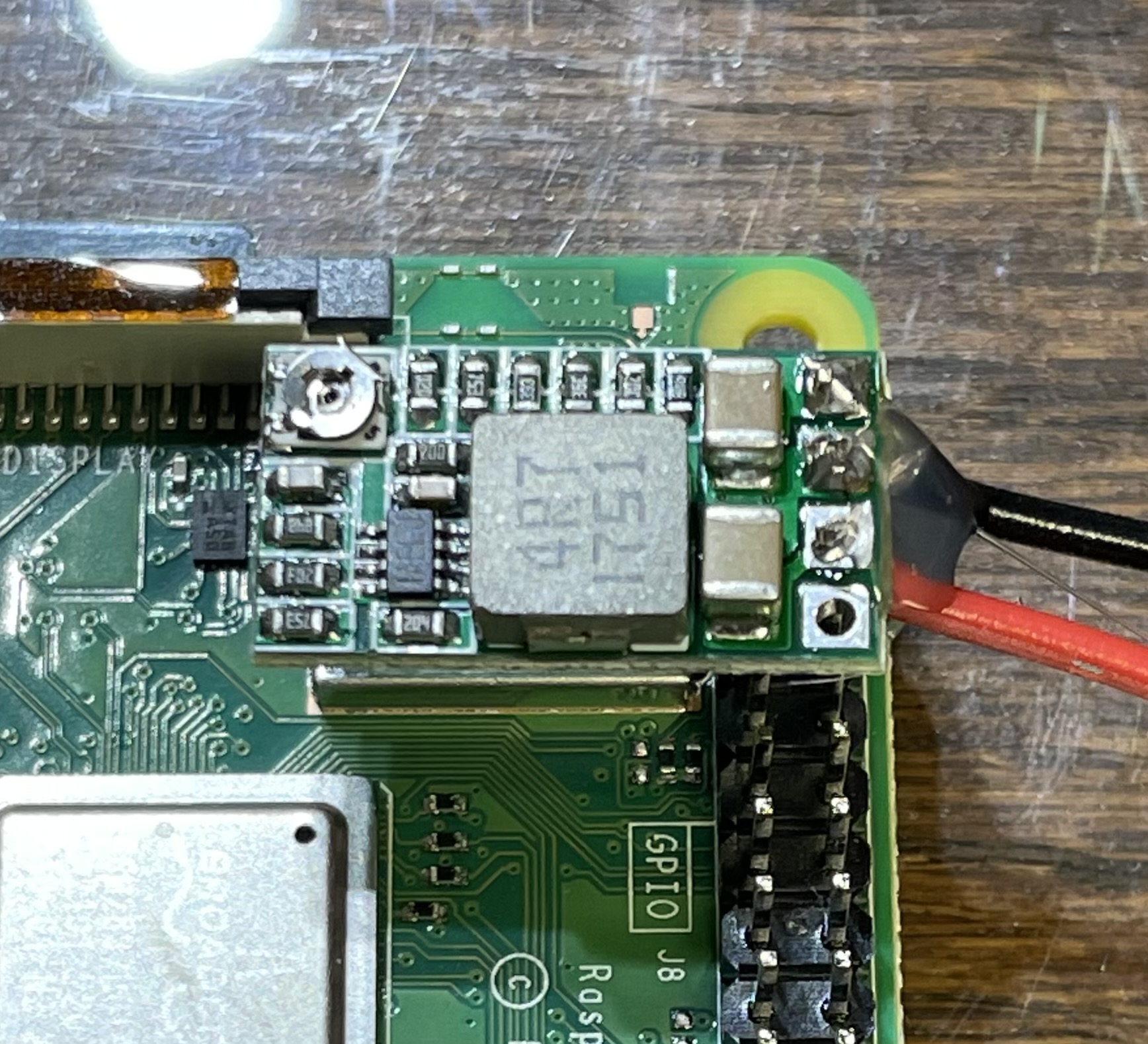
The 5v outputs align perfectly with a 5v and Ground pin on the Raspberry Pi GPIO, so all we need to do is solder a 2-pin header to it. One small glitch is the shared ground, so I have to sneak a ground wire in along with the ground pin on the header. The header looks a bit rough because it is recycled from some larger headers I have in my scrap pile. I just snip off the pins I need using side cutters.
In the picture above, the pads are:
[O] Power Out + (5v)
[O] Ground – (Shared)
[O] Power In + (4.5-24v)
[O] Enable (Unused)
Important: The regulator has “fixed” voltage settings you can choose using solder pads and by either cutting a trace on the back or pulling off the wiper on the voltage adjustment potentiometer. You can see the voltage adjustment pot in the upper-left corner of the board in the first picture below, and you can see the fixed voltage resistor pads on the back in the 2nd pic. DON’T DO IT! I wasted four of them. Their resistance values aren’t very accurate and you will likely end up (like I did) with a regulator that is putting out around 4.3v instead of 5v! The best thing to do is hook it up to your expected input voltage and adjust the output to 5v using a meter and the adjustment pot.
So, all I do is solder the header and input voltage wires to the appropriate pads, set the output voltage (above), and slip it on GPIO pins 4 and 6 (2nd and 3rd pin on the outside row) on the Raspberry Pi. Just to keep the whole thing stable- I use a bit of hot-melt glue on the header and GPIO. This prevents it from moving around or coming off.


The regulator/buck converter is small enough that you can still fit the Raspberry Pi in most cases that support GPIO headers if you want to. Otherwise- it’s unobtrusive in whatever mount you are using for it.
It might be unnecessary if you have a good stable 5v power source otherwise, but it’s good added security, especially since the power sources these are connected to are also powering pixels or P10 panels.
As an alternative- you can of-course either butcher a micro-USB cable or get a micro-USB break-out/terminal adapter to feed power through the Pi’s micro-USB port, using the Pi’s internal regulator if you are running 5v PSUs. The thing is- at ~$0.75 each- these are actually cheaper! You can also use the same regulator for 12v systems.