
D1 Mini E1.31 (DMX) Relay Controller
I wasn’t content to just be able to run RGB pixels, I also wanted to be able to programmatically turn the system on and off. I could use some off-the-shelf home automation gear, but it seemed overly-complicated to try to drive it from FalconPlayer (FPP). Of course I could also use old-school programmable timers, but that wasn’t a very elegant solution.
What I really wanted was the ability to have my light show turn itself on and off. So- turn the system on just before playing my playlist, and then turn if off after the playlist (or scheduler) is done.
So, I want a 120v relay controlled by the same type of hardware as the rest of my show, so- the D1 Mini!

D1 Mini Side 1 D1 Mini Side 2
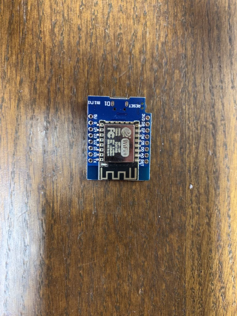
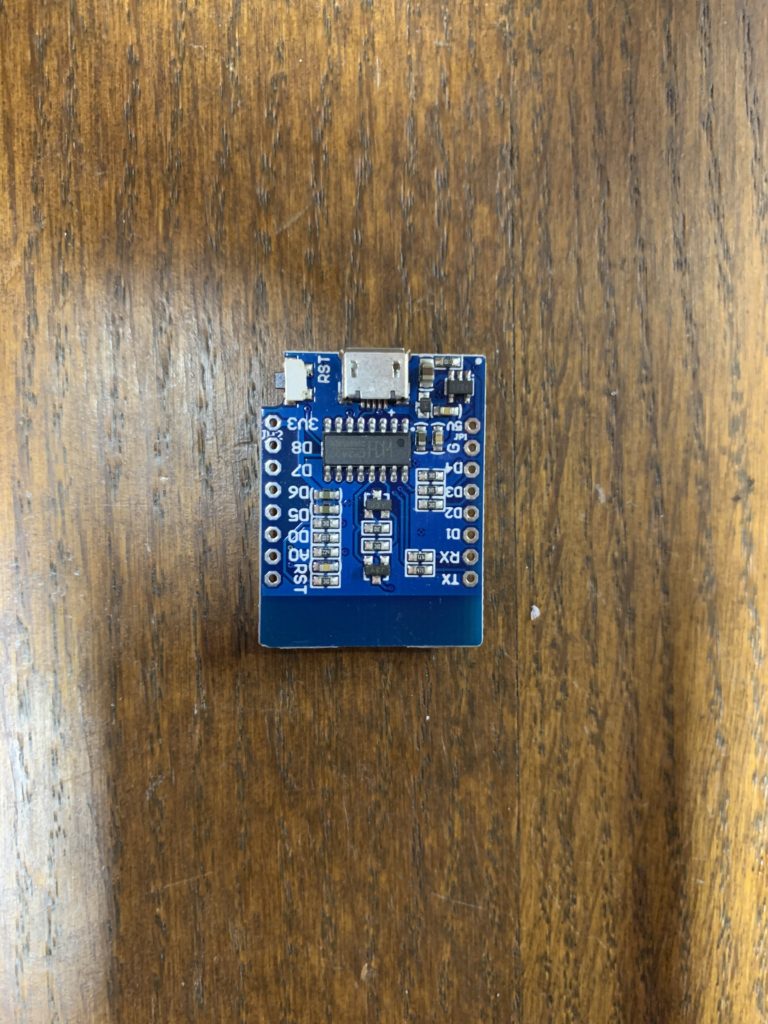
The D1 Mini is an ESP8266-based “Node MCU”. It’s a microcontroller with built-in WiFi- perfect for building WiFi lighting controllers. You can buy them on Amazon or from Chinese retailers- just look for “WEMOS D1 Mini” (WEMOS was the original manufacturer, but they are cloned by a number of companies.) Be sure it is the complete board (with MicroUSB port and Reset button). You can generally pick them up for a few dollars each or less, usually in 5-10 packs (and you want a bunch of them!)
You will also need a “D1 Mini Relay Shield”, which again you can find through a variety of online retailers.
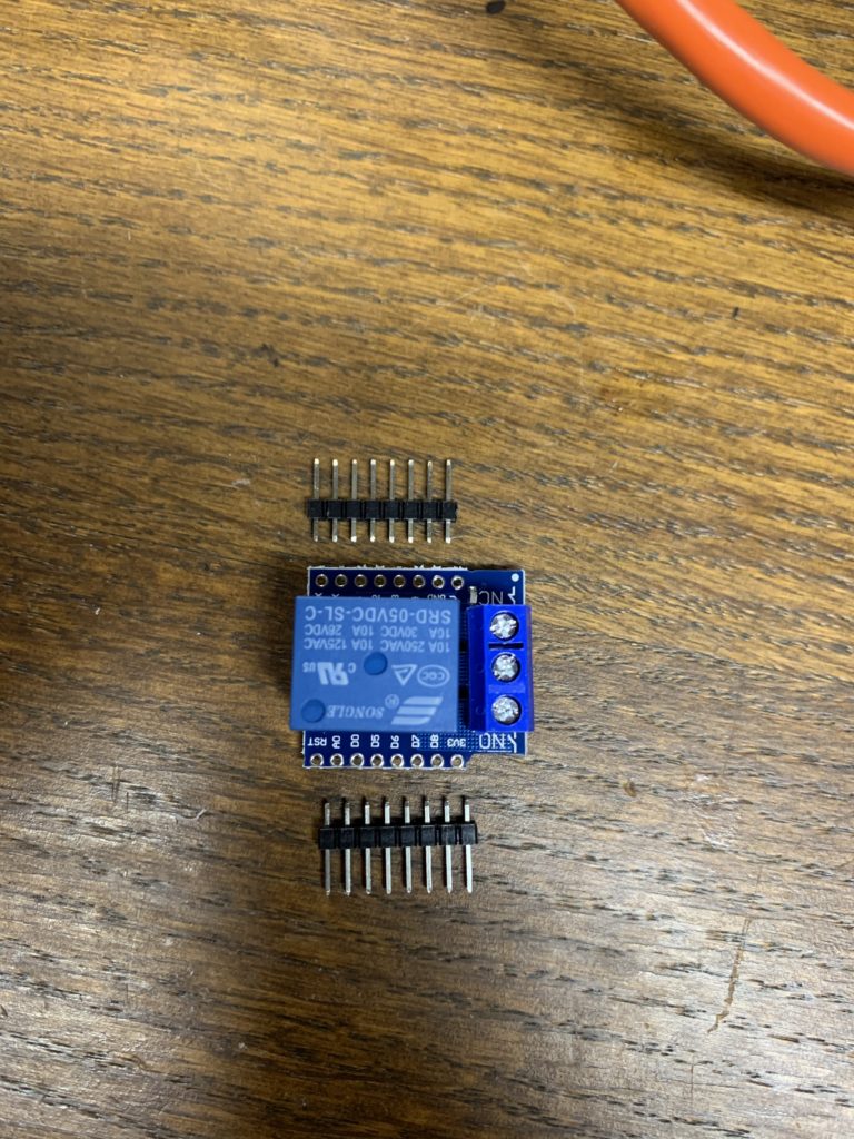
These are pretty-much ALL 120vAC 10A, but double-check the specs. They are designed to be soldered on top of the D1 Mini using the supplied stand-offs.
Here’s one trick, especially if soldering isn’t your forté. The relay only uses THREE pins- “+5v”, “G”, “D1”. I usually just solder those three and “TX” on one side, and “RST” and “3V3” on the other. That gives enough support for the relay, without wasting time on pins that aren’t even used.
In my pic- I only showed one set of standoffs. There is another set of “socket” standoffs that you actually solder to the D1 Mini. This allows you to separate the two if you need to replace one or the other.
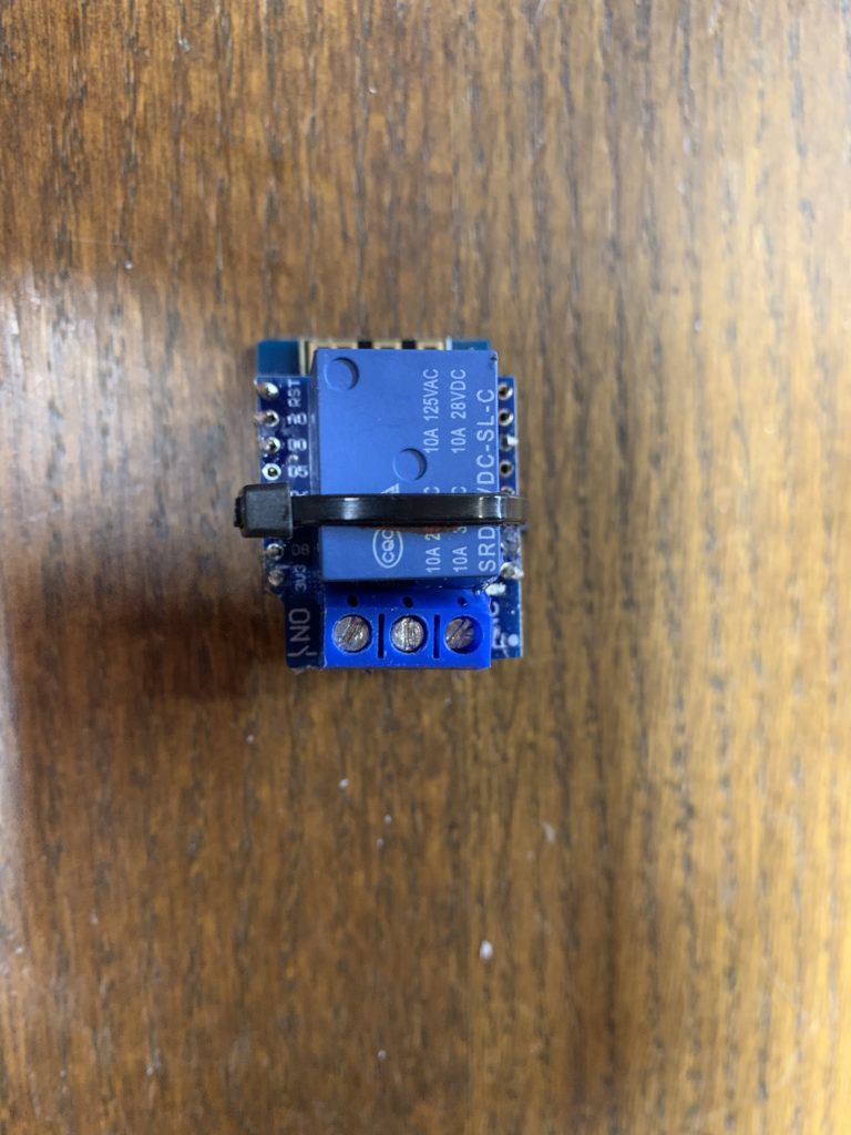
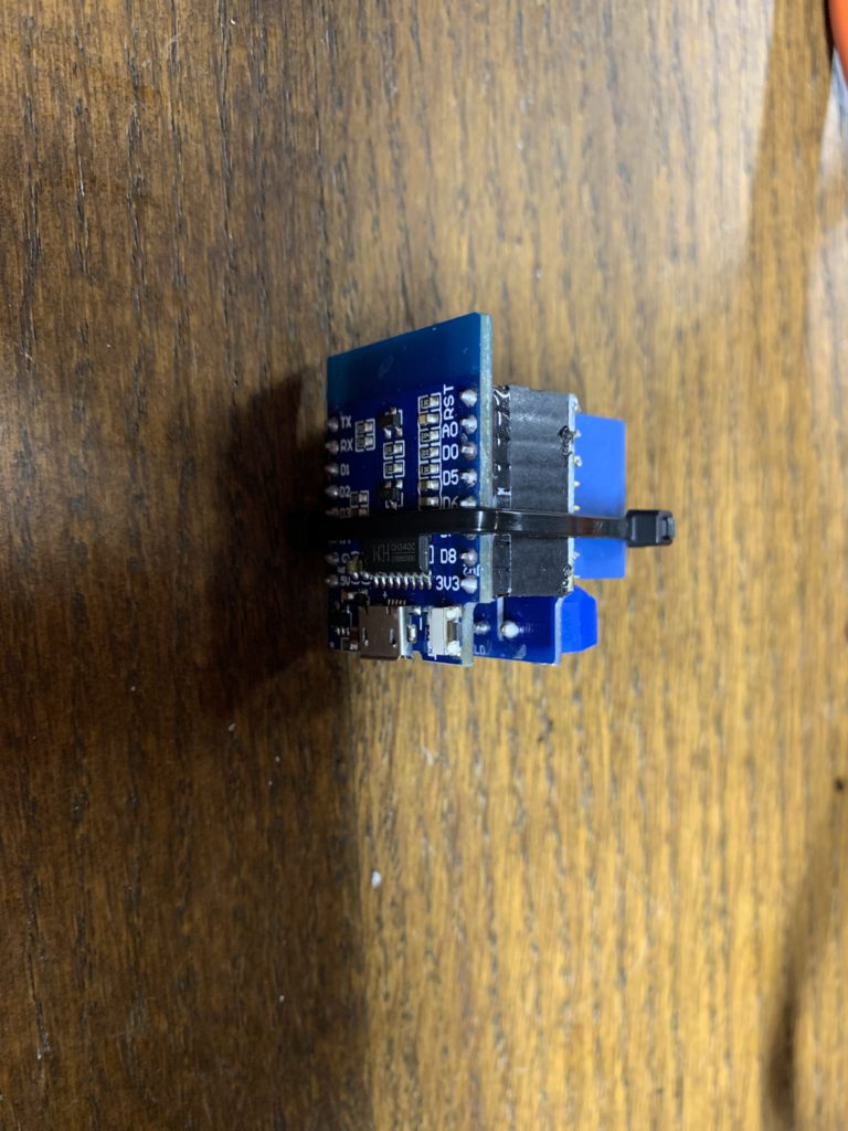
Once you are done soldering, you will end up with something like this…
D1 Relay Top D1 Relay Side
Before I go any further- I need to cover programming the D1 Mini. It isn’t too difficult, but I’m also not going to get into a whole tutorial on using the Arduino IDE. There are a LOT of resources online. I just want to cover the specifics for this application.
First, you can download the Arduino IDE and get lots of information about Arduino, and Arduino-like, microcontrollers here:
https://www.arduino.cc/en/Main/Software
The Arduino IDE runs on Windows, Mac, and Linux. I use a Mac, so some pictures are Mac-specific, but are similar to Windows. Just download and install/run it. For Mac users on Catalina or later- you will have to deal with the usual security bypasses.
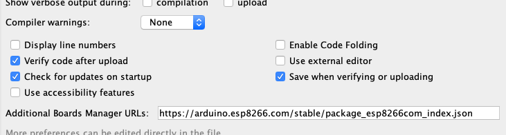
After you launch it, you need to add the ESP8266 board configurations to it. This is pretty easy- just open up Arduino -> Preferences and look for:
“Additional Boards Manager URLs:”
Add the following URL to the field:
https://arduino.esp8266.com/stable/package_esp8266com_index.json
That’s it- now you can go to Tools -> Board -> Boards Manager, and install the “ESP8266” boards. When done, you can select:
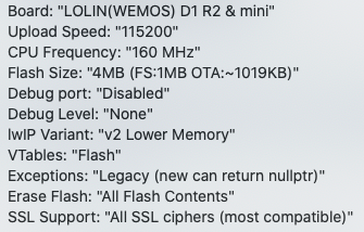
“LOLIN (WEMOS) D1 R2 & Mini” or similar if you know the exact board you have.
Here are my D1 Mini board settings, as of this post:
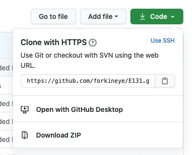
You will also need to install a special “Library” called “E131.h”. You can download it here:
https://github.com/forkineye/E131
Just look for the green [Code] button, click on it, and select Download ZIP
Now, in Arduino- select:
Sketch -> Include Library -> Add .ZIP Library
Browse to your downloads folder and select the file you just downloaded.
If you made it this far- congratulations! You just made it through the “hard” part! The good thing is- these settings also apply to installing ESPixelStick (Pixel Controller) on the D1 Mini.
Now- create a new “Sketch” (Program) and call it something like “D1_Relay_Controller”. Copy and paste the following into it:
UPDATE: 9/18/2020
I had to modify this a bit. I found the (old) E131.h library’s WiFi connection didn’t work very well for some reason for a new AP I installed for my show. I had to add WiFi connection code before setting up the E1.31 connection.
#include <ESP8266WiFi.h> // a library to include
#include <E131.h>; // a library to include https://github.com/forkineye/E131
//Set your WiFi network information below...
const char* ssid = "My_WiFi_Network"; // your network AP SSID
const char* password = "My_WiFi_Password"; // your network AP password
//Set the universe and channel you want to use. Universe is E1.31 (DMX) universe.
//Channel will generally be 0, which is actually 1 (Red) in DMX. Use 1 for Green, and 2 for Blue.
const int universe = 5; // universe to listen to
const int channel = 0 ; // channel to use - these are 1 lower than normal (0 = 1)
// Un-comment the following if not using DHCP, and edit accordingly.
// Important: Those are commas, not periods!!! This is just the way the IPAddress datatype works.
//const IPAddress ip(10,0,0,245);
//const IPAddress netmask(255,255,255,0);
//const IPAddress gateway(10,0,0,1);
//const IPAddress dns(8,8,8,8);
//See below to set Multicast or Unicast. Default is multicast.
int channel_val; // the current value of the channel we are using, don't change this.
long int num_ch_in_pkt; // number of channels in the recieved packet, don't change this.
int output_1 = 5; // names the ESP8266 GPIO output pin we are using (5 is D1 !!!), don't change this for Relay Shield.
E131 e131;
void setup() {
Serial.begin(115200);
Serial.print("Connecting to ");
Serial.println(ssid);
//If you want to use a fixed IP address instead of DHCP, un-comment the following...
//WiFi.config(ip, dns, gateway, netmask);
WiFi.begin(ssid, password);
while (WiFi.status() != WL_CONNECTED) {
//Loop (forever) until WiFi is connected.
delay(500);
Serial.print(".");
}
//Set output pin and set it high (off).
pinMode(output_1, OUTPUT); // set pin as an output
digitalWrite(output_1, HIGH); // set pin to high
// **** Pick one. You can either use Unicast or Multicast. If you don't know which- pick Multicast. ****
// e131.begin(E131_UNICAST, universe); //Unicast (TCP)
e131.begin(E131_MULTICAST, universe); //Multicast (UDP)
}
//Don't change anything below...
//Any DMX value under 127 is "Off", above 127 is "On".
void loop() {
num_ch_in_pkt = e131.parsePacket(); // parse packet
if (num_ch_in_pkt) { // if num_ch_in_pkt &gt; 0
channel_val = (e131.data[channel]);
Serial.println(channel_val);
if (channel_val > 127) {
digitalWrite(output_1, HIGH); // SSR on
}
else {
digitalWrite(output_1, LOW); // SSR off
}
}
}In the code above- you want to change a few things…
const char* ssid = "MyWiFi_SSID"; // your network AP SSID
const char* password = "MyWiFi_Password"; // your network AP password
const int universe = 1; // universe to listen to
const int channel = 0 ; // channel to use - these are 1 lower than the DMX channel!
First- replace “MyWiFi_SSID” with your WiFi network name (the WiFi network you are running your show from.) Be sure to keep the quotes.
Next- replace “MyWiFi_Password” with the password for the above WiFi network. Be sure to keep the quotes.
Important: The D1 Mini can only access 2.4Ghz WiFi networks, not 5Ghz, so be sure to use an appropriate network.
You should use a separate show WiFi network, on a dedicated WiFi AP/Router. Don’t just add your light controllers to your home WiFi- you WILL have issues. I also recommend you set it up as a “hidden” network- look for a “Don’t Broadcast SSID” or similar option on your AP/Router.
This sketch doesn’t have a Web management page, so you can only set the WiFi network via Arduino IDE and USB. Keep this in mind before you “seal up” your relay controller.
You also want to set the universe and channel for the relay. Here is where you need to make a decision…
You have almost unlimited E1.31 Universes, so the most straightforward way to do this if you are going to use multiple relays is just to use a Universe for each one. So “Relay 1” might be Universe 1, “Relay 2” would be Universe 2. You would just set “universe = 1”, and “channel=0” Channel 0 translates to “Red” on many light controllers, or it will actually be called “Channel 1”. Internally it is 0 though, which can be a bit confusing.
UPDATE – October, 2020:
After a number of problems as my show grew in 2020- I found out you DO NOT want to waste universes like this. A show runner will send out all programmed universes, and generally all channels in that universe, so you can waste a huge amount of network bandwidth on almost-empty universes. You are better off doing the below- assign one universe to all your relays, and assign consecutive channels to them. Just remember to subtract 1 for the channel you assign on the D1 Mini…
I use Universe 1 for all of my “power” channels. Let’s say you set “universe=1” and then set a different channel for each one. You will end up with something like:
Relay 1 = U1, C1 “Red” (channel = 0 on D1 Mini)
Relay 2 = U1, C2 “Green” (channel = 1 on D1 Mini)
Relay 3 = U1, C3 “Blue” (channel = 2 on D1 Mini)
Relay 4 = U1, C4 “Red” (channel = 3 on D1 Mini)
Relay 5 – U1, C5 “Green” (channel-4 on D1 Mini)
…and so-on.
Just remember- the channel you program will be -1 from the actual DMX/E1.31 channel, and you will need to keep track of the channel number and possibly color for your lighting controller. While the colors are technically irrelevant, many show runner or DMX test programs/apps think in terms of RGB and assign channels by those three colors. If yours doesn’t disregard the color and just use the channel numbers as-is.
If you are not using DHCP and Multicast, you will want to set IP address parameters by uncommenting the following lines and editing them. Note that because of the way Arduino reads IP addresses, use commas instead of periods between numbers.
// Important: Those are commas, not periods!!!
IPAddress ip(192,168,1,101);
IPAddress netmask(255,255,255,0);
IPAddress gateway(192,168,1,1);
IPAddress dns(8,8,8,8);
There are other options below as far as selecting DHCP and/or Multicast. I’m not going to get into either of those. You generally always want to use “Unicast” for WiFi and a fixed IP address. If you can’t configure your AP/Router with a block of fixed IP addresses (outside the DHCP range)- you will need to figure out what IP address your relay is using every time you connect it. (Sometimes it will be the same, but not always.) The Serial Monitor will show this, although that won’t help once your relay is installed somewhere. Your AP/Router should also have a way to display “Client Connections” in its Web management system.
Update, 2021:
While my years as a network administrator have given me an affinity for fixed IPs when practical for things like controllers, using Multicast you don’t really care what the IP is. So- for these anyway- I just set them for DHCP and use Multicast. The reason is this- I often embed these controllers and they aren’t easy to get to, so changing a fixed IP address is a pain in the @$$! As long as my WIFI SSID and password doesn’t change, the IP addresses don’t matter. So- my preferred configuration for these is now DHCP and Multicast. I’ve edited the code above accordingly. As they only need to be sent a single “on” and “off” command over a long period of time anyway, there isn’t a lot of network traffic generated over WIFI for them. Live and learn… 😀
Once you have finished editing things, you are ready to upload your Sketch to the D1 Mini. Plug it into your computer using a Micro-USB cable. You might see a brief flash of a blue LED next to the WiFi antenna, but otherwise not much will happen.
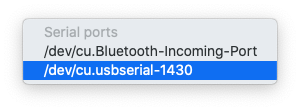
In the Arduino IDE, you should be able to pick the “Serial Port” it is connected to via USB. Select Tools -> Port and choose it from the menu. Look for “USB Serial”. On a Mac, it will look something like this:
Now- just click on the little right-arrow icon in the upper-left corner of the Arduino IDE. This will compile your Sketch and upload it to the D1 Mini. It should only take about a minute.
If it is successful- you should see something like this in the bottom pane of the Arduino IDE:
Wrote 274800 bytes (202372 compressed) at 0x00000000 in 19.6 seconds (effective 112.3 kbit/s)...
Hash of data verified.

Leaving...
Hard resetting via RTS pin...
If not and you see errors- double-check the changes that you made. If anything- start from scratch with a new Sketch, and cut-and-paste the code above again. If it is a serial port error- you will likely have to Google solutions. The first time you flash the D1 Mini- DO not enable the Serial Monitor (see below). This may interfere with flashing (loading) your Sketch.
One big thing- be sure you have a Micro-USB cable that supports DATA! Many are charging-only and don’t have the data wires. You may need to try a few cables!
When done- you can verify it is working by opening Tools -> Serial Monitor. Press the reset button on the D1 Mini. You will see a bit of gibberish, followed by WiFi connection messages, and eventually, a “Connected with Static IP:” message with the IP Address you set above.
Again- if there are any errors, Google is your friend. If you don’t see anything, or nothing but gibberish in the Serial Monitor- be sure it is set to the same “baud” (speed) as the D1 Mini. In my case- I set both to “115200”. You set the speed of the D1 Mini in the Board Configuration section in the Arduino IDE Tools menu. You can change the BAUD of the Serial Monitor using the drop-down option at the bottom of the window.
Also double-check your SSID (WiFi) network name and password, and note the IP Address, especially if you are using DHCP.
So, now what?
Now you want to test it to make sure it is working. You need to set a controller up with the universe and channel(s) you configured. If you set the channel to any value above 127 (half-way)- you should hear the relay click to On. In some cases, you may see an LED light up on the relay board (if it has one). Anything less than 127 will turn it Off.
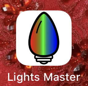
You can do this through the Test options in xLights or FPP (FalconPlayer). If you have an iPhone, there is a great little app called “Lights Master” that I use a lot. It’s a paid app ($8 US), but has been well worth it for me. You can test your whole show using it. You just program in your controllers (like your D1 Mini Relay), and then you can use the “Single Channel Controls” to test your relays, or “Light Colors” or “Light Patterns” to test your RGB pixels.
There are other “DMX” or “E1.31” test apps available for Windows, Mac, iPhone/iPad, Android, etc.
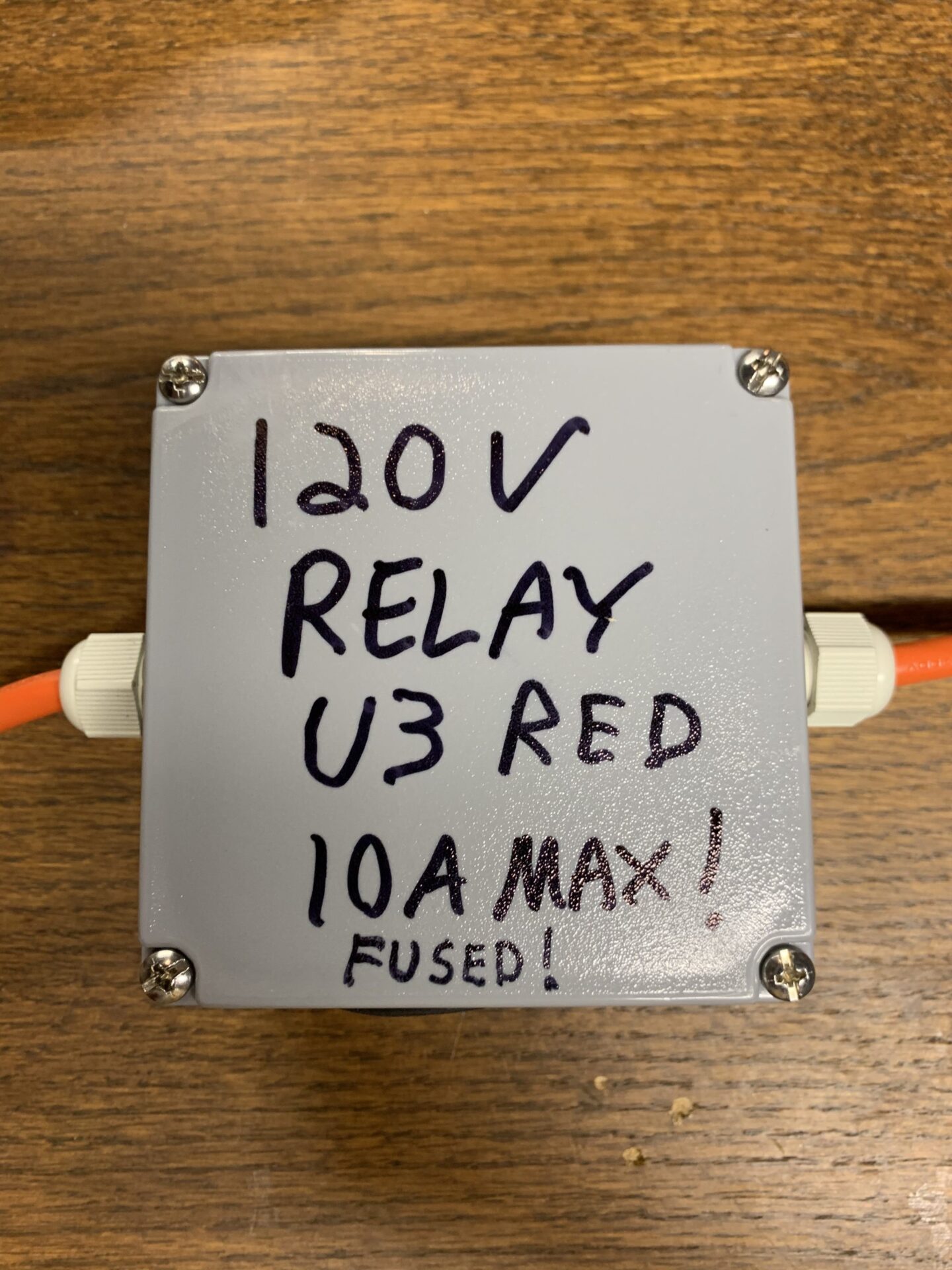
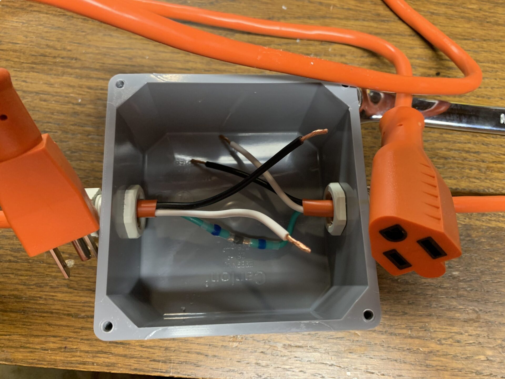
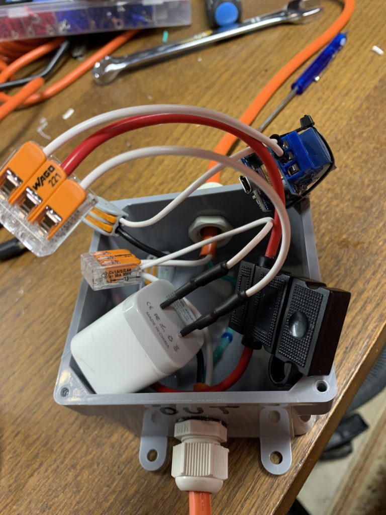
Once you have things working, you probably want to install your relay into some kind of a box. Here is what I did…
Cut a cheap outdoor extension cord in half. Install cable glands in a waterproof junction box and feed both halves through. Strip the outer jacket back to expose the individual conductors. Strip and join the green “Ground” conductors using a solder-seal connector, butt-splice crimp, WAGO connector, or wire nut.
Below I am going to refer to the “IN” and “OUT” sides:
“IN” is the Plug or “Male” side- the one with the blades.
“OUT” is the Jack or “Female” side- the one with the slots.
UPDATE: Don’t do this next thing. See below…
Connect the IN black (HOT) connector through a fuse holder. Fuse at 10A (maximum for relay).
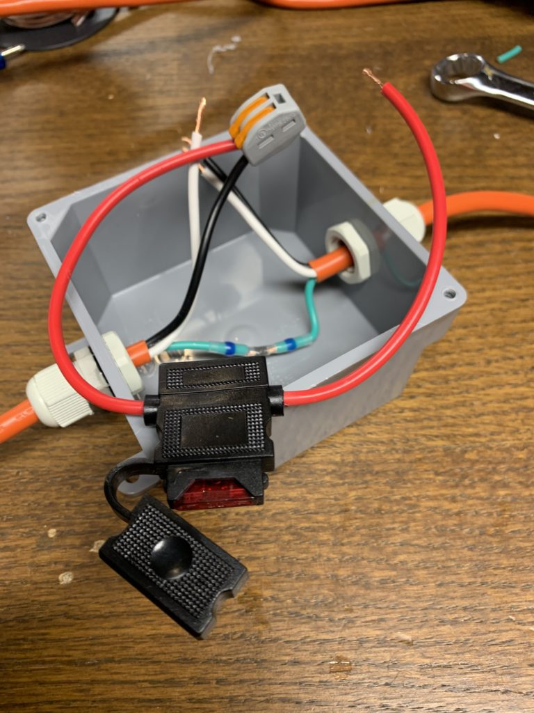
Note- an Amp is an Amp no matter what the voltage! A blade fuse and fuse holder are just fine in this case.
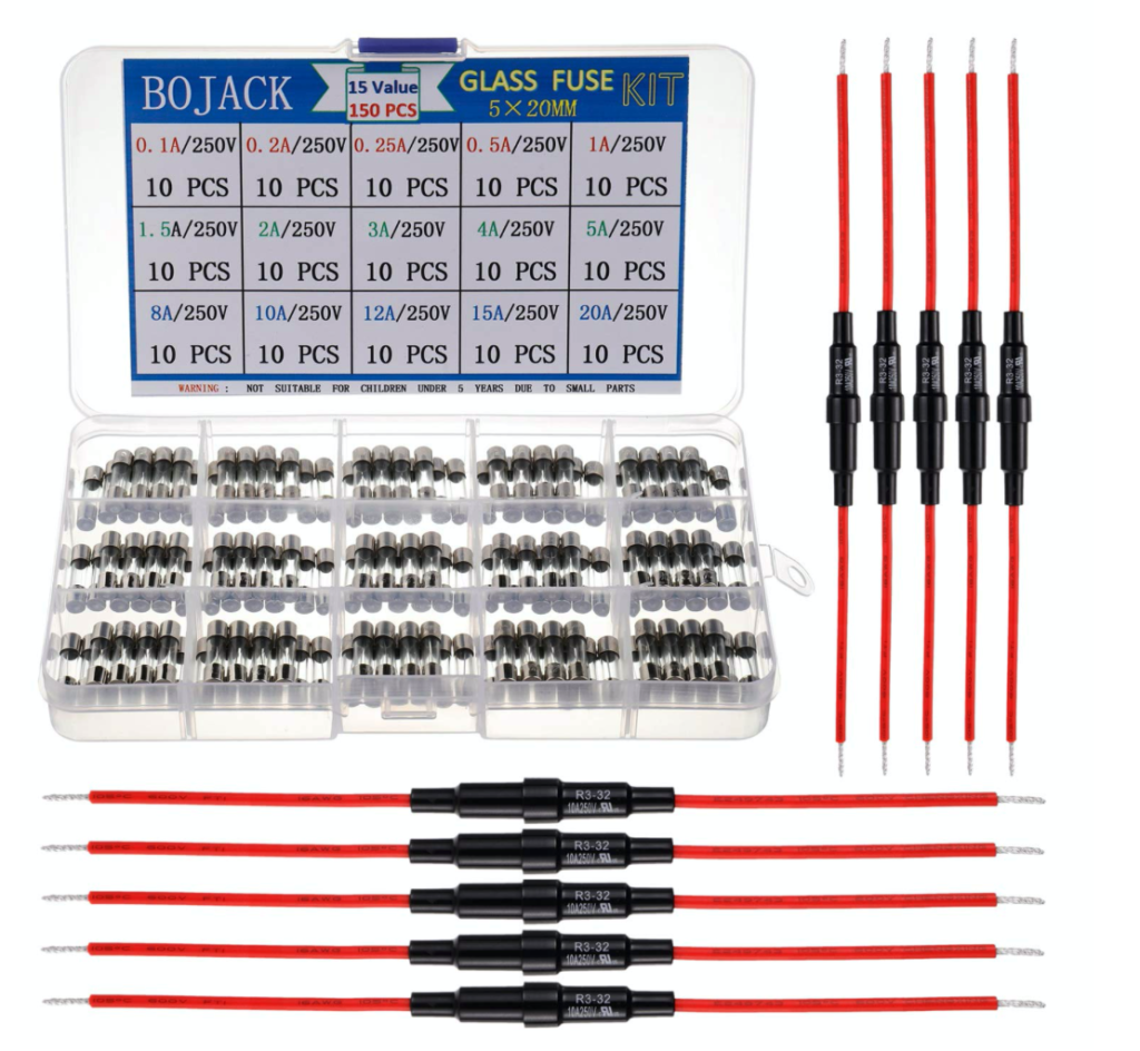
UPDATE:
While an Amp is an Amp, all fuses are not created equal. Using a 12v fuse in a 120v circuit is just a bad idea. It will likely melt or burn before it blows, and at a much lower current than it is rated for.
There are very-specific reasons not to use a AC fuse for DC current, but the opposite is generally fine if the fuses are rated properly, and these blade fuses aren’t.
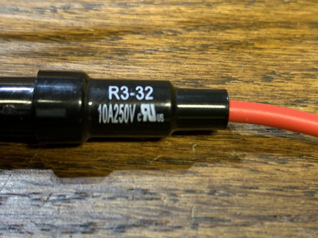
I’m replacing them with these:
Next- connect a USB power adapter up to power. See my USB Power Adapter Hack: https://lunardenlights.com/2020/08/04/power-adapter-hack/
Note: I’m using 16Ga silicone-jacketed chassis hook-up wire for this. I only have a spool of white- so that’s what I am using. Please ignore the white color, as it is used for the “Hot” side too.
You are hooking one blade of the adapter up to IN Black (HOT) (from the fuse holder) and the other to the IN White (Neutral) and OUT White (Neutral) wires. I use 3-way WAGO connectors for this.
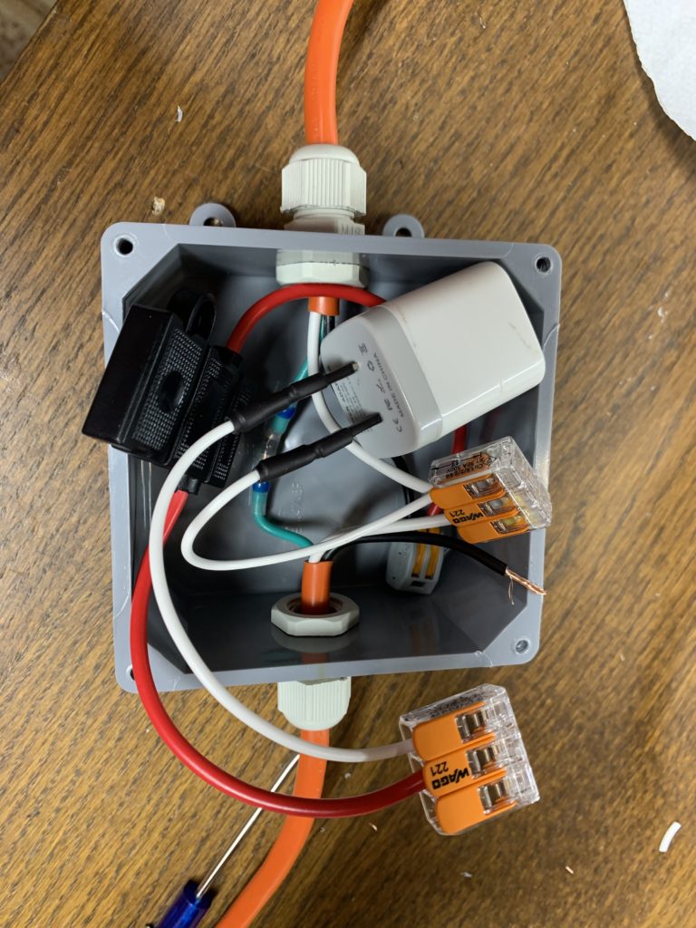
Now, connect the “NO” (Normally Open) and “C” (Common) terminals on the relay between the fuse IN Black (HOT) and the OUT Black (HOT) wires. The relay acts as a switch between them. I’ve found these help out a lot with the relay terminals, which are a bit finicky.
Hopefully that isn’t too confusing. Just remember that Green (Ground) and White (Neutral) need to pass from one side to the other. We need to power the USB adapter from the Neutral wires as-well. The incoming Black (HOT) wire needs to power the USB adapter and then go to the relay to be switched. The outgoing Black (HOT) wire is just connected to the relay, which switches it on and off.
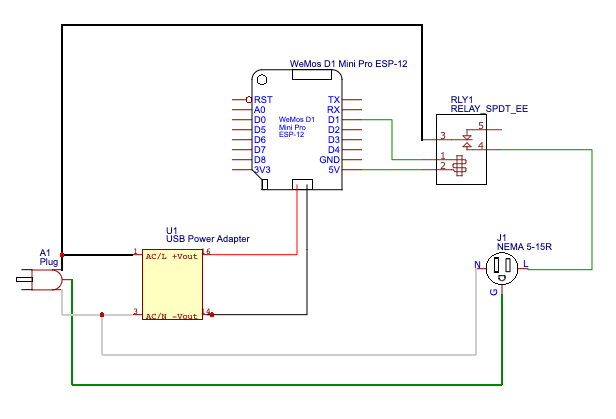
Update:
I finally did a quickie wiring diagram. The D1 Mini to Relay connection isn’t really accurate, but is just a representation. The Relay module is actually opto-isolated.
You can buy really-short (~4″) Micro-USB cables online. Here is the final result, all “gently” stuffed into the box:
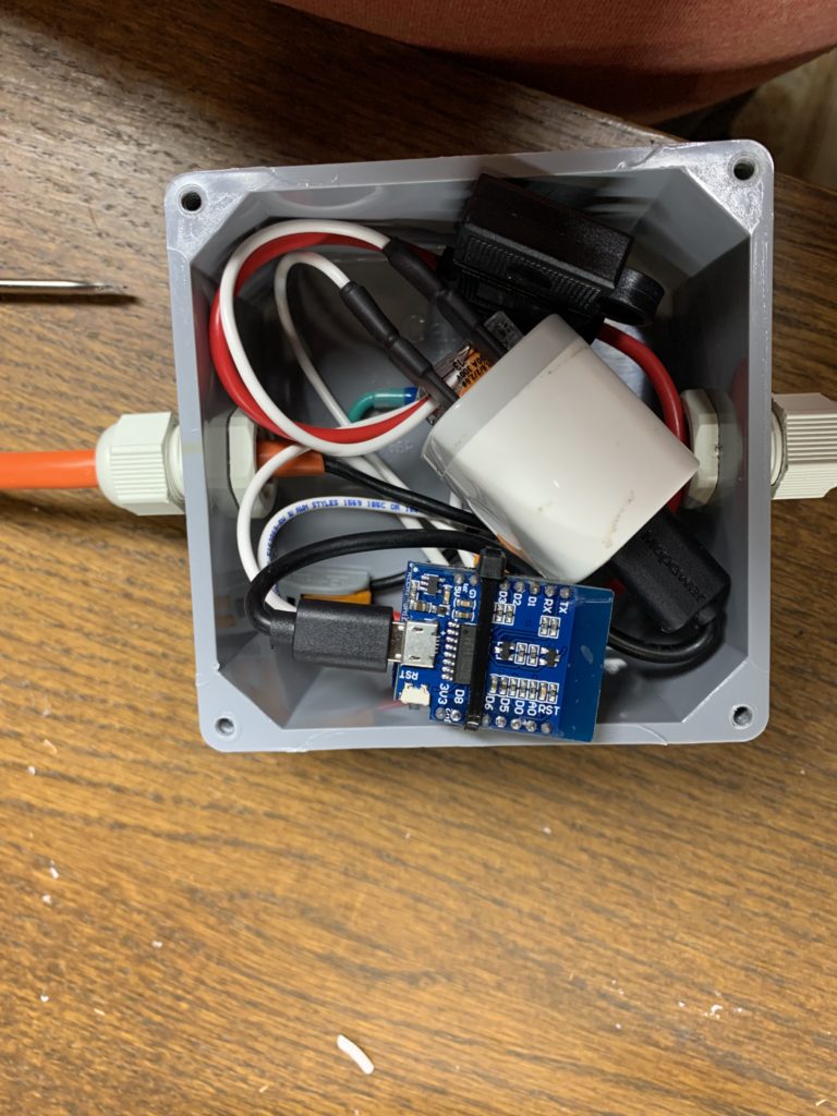

I have several of these that I use to toggle “dumb” display elements on and off. I also use them toggle my display PSUs on and off. I have a script in FPP that toggles everything on at the beginning of a playlist, and then off when it is finished (or when the scheduler stops it).
I don’t want to get into how to configure FPP here. In short: download and edit the “StaticOn” and “StaticOff” scripts from the Script Repository in FPP, and read up on “Pixel Overlay Modules”.
To use these to toggle “dumb” lighting and other elements- set up their universes and channels in your sequencing software (like xLights), and sequence them accordingly. Remember that by default- if Channel 1 (Red) is below 127 (50%) the relay will be OFF, and above 127 it will be ON.
UPDATE:
I changed the way I address these, as wasting a whole universe for 1 channel was just ridiculous, especially since E1.31 sends the entire universe worth of data every time, and not just the single channel. I also incorporated FrankenPower into my display, so I have a lot more relays to work with. I set them all up on a single 30-channel universe. Each one is just on its own channel, and is set up accordingly in xLights and FPP.
I’m using these stand-alone relays to control power to all of my pixel PSUs. FrankenPower runs inflatables, blow-molds, and other conventional props. That way I can easily choose what to turn on and off.