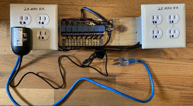
FrankenPower v.2
Important Notice
This site is no-longer being maintained, and the content and links found here may be irrelevant and outdated. It is online for archival purposes only.
Well, I couldn’t come up with anything else to call it. I also didn’t post anything about v.1 so I cover it a bit below.
Earlier this year, I decided to buy an 8 channel relay board for Arduino/Raspberry Pi. My plan was to use it to power our inflatables and other “dumb” yard decorations. The thought was I can turn off the inflatables and maybe add the dumb light decorations to the show somehow.
In more recent discussions with my boss (my wonderful wife), we are thinking of moving a lot of that stuff to our large side yard this year, so there really wouldn’t be any reason to mess with them. So- right now anyway, I don’t really have anything to use this thing for. In any case- I’m trying to post build info in case it helps others so…
I started off wiring up a Raspeberry Pi to the relay board, and then wiring the relays to outlets.
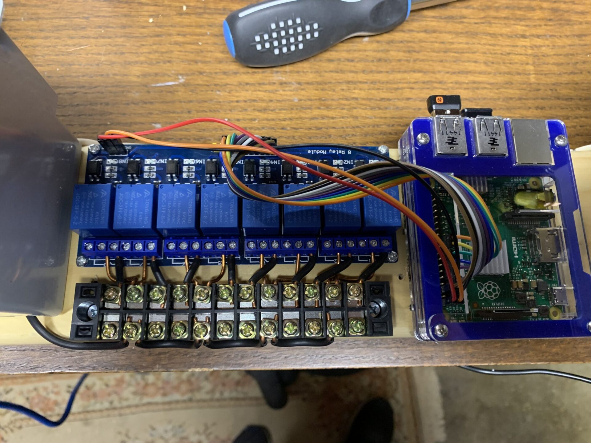
So, since I didn’t do detailed build documentation for this- I want to cover a few things because I found a LOT of conflicting and confusing information about these relay boards.
Here is the relay board I got. All of this applies to the 2, 4, and even most single relay boards for “Arduino” or Microcontrollers.
https://www.amazon.com/dp/B01HCFJC0Y/ref=cm_sw_em_r_mt_dp_HqOBFbG0KTHZV
I want to quote one thing from the description…
Standard interface that can be controlled directly by microcontroller (Arduino , 8051, AVR, PIC, DSP, ARM, ARM, MSP430, TTL logic)
ALL of the instructions I found online insisted that you need to add additional components (transistors and resistors) to provide logic leveling and additional isolation for these boards. No. No you don’t. It’s possible they were for older versions or something, but the modern ones are opto-isolated and have inputs specifically made to be driven from GPIOs. Those transistors everyone insists you need are right there on the board.
Okay, that said- here is what you do need to do though. Again- I found a lot of confusing/conflicting information out there…
You will find a separate jumper/connection area with “VCC” and “JD-VCC” pins, often along with a GND (Ground) pin. There is usually a jumper between VCC and JD-VCC factory-installed. This is for using 5v logic, which the Raspberry Pi and NodeMCUs don’t do. The input circuit is designed to work with anything larger than about 2v, BUT the relays themselves need 5v of coil voltage to activate reliably. They may from 3.3v, but not reliably. This is why the boards have TWO input voltages:
JD-VCC is the coil voltage. This should be 5v.
VCC is the logic-level voltage. For the RPi and NodeMCUs- it’s 3.3v.
Fortunately- the Raspberry Pi AND NodeMCUs (Dev boards, like the D1 Mini) already have both voltages available. The relay coils only use about .072A each, which means energizing all 8 at once is only a little under .6A. So you can actually run it off the 5v USB rail if you use a good power supply. I’m using a 3A one for this.
So- pull the factory jumper between JD-VCC and VCC, and connect a wire from a 5v source, like a 5v GPIO, to “JD-VCC”. Then connect 3.3v from a “3v3” or similar GPIO to “VCC”. Connect one of the GND (Ground) pins on the relay board to a GND GPIO pin. Usually there will be a couple of different GND pins- they are all connected.
Then, connect the GPIOs you want to use to the “In” pins for the relay board. 1-8 in this case. Unfortunately since I have revised this- I don’t remember what GPIOs I used on the Raspberry Pi. Any that can be set as Output and that are all either high or low on boot is what you want. Some of them will come up high or low, and then switch during boot.
Here are a couple more pics of the original build…
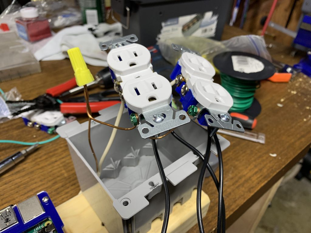
I cut the hot jumpers on the right sides of the outlets, so each one can be wired separately. All of the commons are tied together, as are the grounds. I used 14Ga stranded wire to hook the outlets up to the relays.
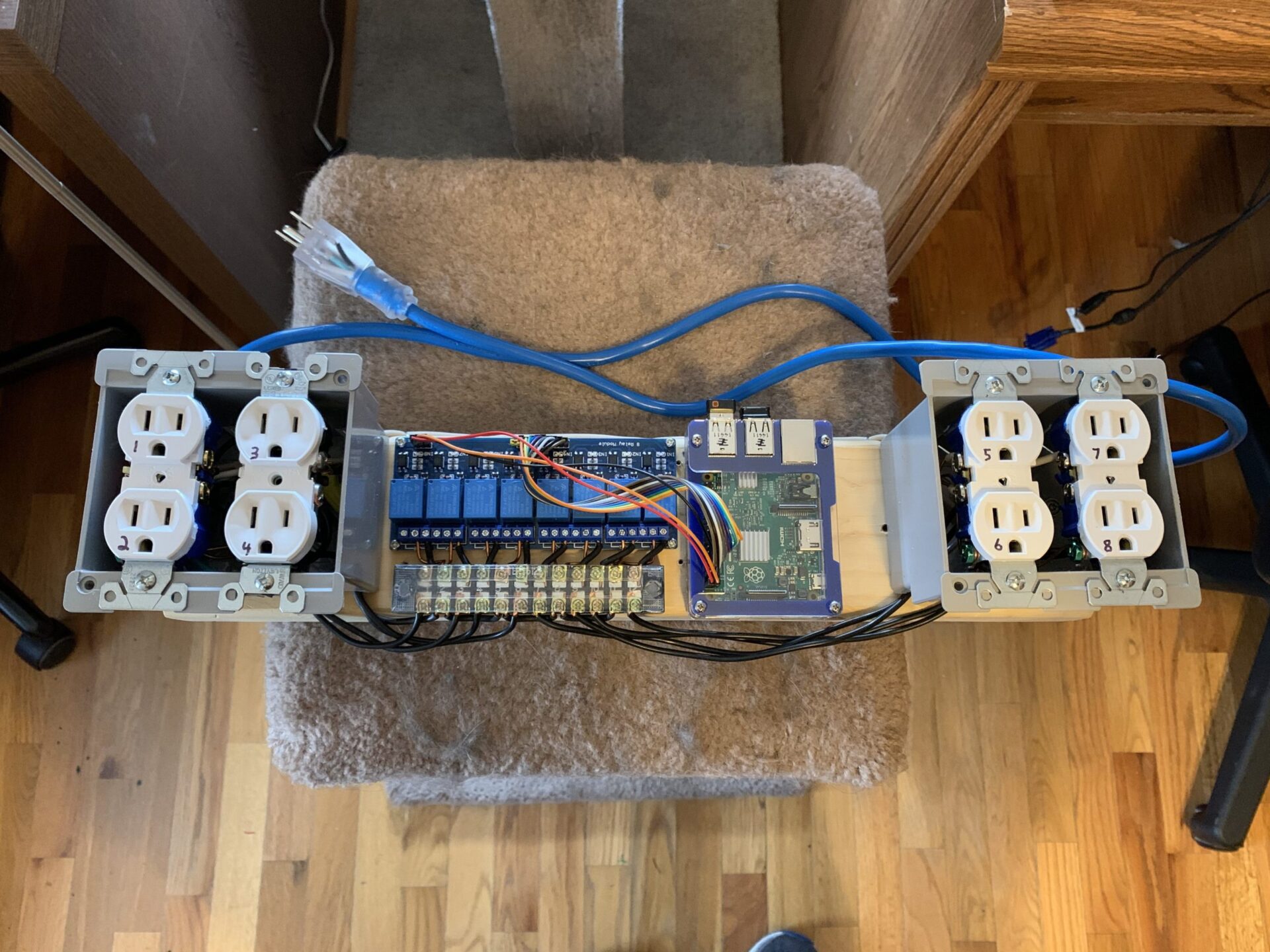
I butchered a 14Ga extension cord to use for power. It is fed through the first outlet box, and tied into the common and ground circuits there. I used a couple of pieces of solid 14Ga common and ground wires to run along the top side of the board between the two outlet boxes.

I didn’t stick with the Raspberry Pi because I couldn’t control the relays via FPP. I think there actually is a way to do it, but I couldn’t find it at the time. At the time- I wrote some shell scripts using WiringPi code that were launched from cron. Basically- I made a fancy 8 channel timer.
Well, it turned out to be 7 channels. For some reason- Relay 7 decided it doesn’t want to work anymore. So- to make lemonade out of lemons- I just decided to use Outlet 7, which is stuck “on”, to power the Raspberry Pi. So- one cord instead of two. You will see that in the later pictures.
I started to dig into whether or not I could actually run the relay board from a D1 Mini. Turns out- you can!
So- I pulled the Raspberry Pi, did some soldering, and now we have “v.2”:
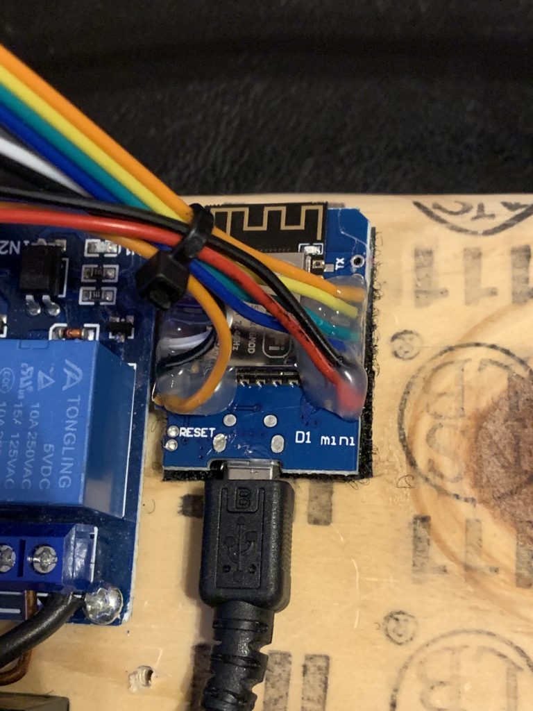
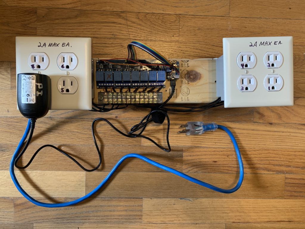
Here is how I wired it up to the D1 Mini…
Remove VCC/JD-VCC Jumper.

Relay Board - Wire Color - D1 Mini

VCC/JD-VCC Power Header:
GND - Black - GND
VCC - Orange - 3V3 (logic level VCC)
JD-VCC - Orange - VCC 5V

Main Relay Header:
GND - n/c
R1 - Orange - D1
R2 - Yellow - D2
R3 - Green - D3
R4 - Blue - D4
R5 - Purple - D5
R6 - Gray - D6
R7 - White - D7
R8 - Black - D8
VCC - n/c
Since I connected power to the power header, there was no need to connect anything to the GND and VCC pins in the main relay connection section. The wire colors don’t really matter as far as the triggers go- they just matched the ribbon of cable I used for the original build.
I had previously written and posted my Arduino code to drive ONE relay using E1.31. I use this for these relay boxes, which I use to power my show LED PSUs on and off. I modified that a bit to handle 8 relays. It can be modified to drive any number of relays. That article also has more details about how to load this on your controller:
/* Modification of old E1.31 single-channel relay controller
 * Supports 8 channels from the starting universe selected.
 * By Wolf Butler
 */

#include <ESP8266WiFi.h> // a library to include
#include <E131.h> // a library to include https://github.com/forkineye/E131

//Set your WiFi network information below...
const char* ssid = "My_WIFI_SSID"; // your network AP SSID
const char* password = "My_WIFI_Password"; // your network AP password

// Comment the following out if using DHCP, otherwise- adjust as-needed.
// Important: Those are commas, not periods!!! This is just the way the IPAddress datatype works.
const IPAddress ip(10,0,0,251);
const IPAddress netmask(255,255,255,0);
const IPAddress gateway( 10,0,0,1);
const IPAddress dns(8,8,8,8);

//See below to set Multicast or Unicast. Default is unicast (TCP).

//Set the universe and START channel you want to use. Universe is E1.31 (DMX) universe.
//Generally you will just use 1-8, so just leave the default of 1.
const int universe = 1; // universe to listen to

//Generally you want consecutive channels starting at 0 (which will be 1 in the controller/control software).
//This MUST match the number of outputs below or bad things will happen.
int channels[] = { 20, 21, 22, 23, 24, 25, 26, 27 };

//Set the output pins here. These are the GPIO pins, and not necessearily "D" pins.
//For example- for the D1 Mini, pin GPIO 5 is "D1". We would enter pin 5 in this case.
//In short- "D" numbers don't correspond to GPIO numbers.

//Example: For D1, D2, D3, D4, D5, D6, D7, D8 on the D1 Mini, use..
//int outputs[] = { 5, 4, 0, 2, 14, 12, 13, 15 }

int outputs[] = { 5, 4, 0, 2, 14, 12, 13, 15 };

//Don't mess with these...
int channel_val; // the current value of the channel we are using, don't change this.
long int num_ch_in_pkt; // number of channels in the recieved packet, don't change this.
E131 e131;
int cval[8]; //Used for formatted output to serial terminal

void setup() {
  Serial.begin(115200);
  Serial.print("Connecting to ");
  Serial.println(ssid);

  //If you want to use DHCP instead of a fixed IP address (above), comment the following line out...
  WiFi.config(ip, dns, gateway, netmask);

  WiFi.begin(ssid, password);
  while (WiFi.status() != WL_CONNECTED) {
    //Loop (forever) until WiFi is connected.
    delay(500);
    Serial.print(".");
  }

  //Initialize the GPIOs and set the relays to off (default- Low)
  for ( int i = 0; i < 8; i++ ) {
    pinMode(outputs[i], OUTPUT);
    digitalWrite(outputs[i], LOW);
  }

  // **** Pick one. You can either use Unicast or Multicast. If you don't know which- pick Unicast. ****
//  e131.begin(E131_UNICAST, universe);   //Unicast (TCP)
  e131.begin(E131_MULTICAST, universe); //Multicast (UDP)

  Serial.println("Waiting for channel data...");
}

//Don't change anything below...
//Any DMX value under 127 is "Off", above 127 is "On".

void loop() {
    /* Parse a packet */
    uint16_t num_channels = e131.parsePacket();

    /* Process channel data if we have it */
    if (num_channels) {
      Serial.printf("\nUniverse %u / %u Channels | Packet#: %u / Errors: %u\n",
      e131.universe,              // The Universe for this packet
      num_channels,               // Number of channels in this packet
      e131.stats.num_packets,     // Packet counter
      e131.stats.packet_errors);   // Packet error counter
      for ( int i = 0; i < 8; i++ ) {
        channel_val = e131.data[channels[i]];
        cval[i] = channel_val;
        if (channel_val > 127) {
          digitalWrite(outputs[i], HIGH); // SSR on
        }
        else {
          digitalWrite(outputs[i], LOW); // SSR off
        }
      }
      Serial.printf("GPIO:Channel Values:\t%u:%u\t%u:%u\t%u:%u\t%u:%u\t%u:%u\t%u:%u\t%u:%u\t%u:%u\n",
      outputs[0], cval[0], outputs[1], cval[1], outputs[2], cval[2], outputs[3], cval[3],
      outputs[4], cval[4], outputs[5], cval[5], outputs[6], cval[6], outputs[7], cval[7]);
    }
}
This works on a D1 Mini, or any other NodeMCU (just modify the GPIOs accordingly). It won’t work with ESP32 without loading different WiFi and E1.31 libraries and adapting the code to work with them. I know it’s possible, I just haven’t messed with it.
Once it is compiled and loaded- we have a WiFi controlled set of relays- if we send anything above 127 to one of them via E1.31- it will toggle on. Anything below and they are toggled off. They use consecutive channels, at least by default, so if you are using an RGB pixel controller:
Node 1, “Red” (Chan. 1) -> Relay 1
Node 1, “Green” (Chan. 2) -> Relay 2
Node 1, “Blue” (Chan. 3)-> Relay 3
Node 2, “Red” (Chan. 4)-> Relay 4
Node 2, “Green” (Chan. 5) -> Relay 5
Node 2, “Blue” (Chan. 6)-> Relay 6
Node 3, “Red” (Chan. 7)-> Relay 7
Node 3, “Green” (Chan. 8) -> Relay 8
I sent a quick test chase sequence to it:
It’s a bit jumpy because I was actually sending the sequence from my phone as I was recording the video. That doesn’t work so well. It can actually run very-very fast otherwise.
Conclusion/To be continued?…
So I’ll be the first to admit that this thing isn’t going to get a UL listing. It is unsafe by most standards. It is a prototype as-is. My thought was I could put it in a waterproof box of some kind and use it as-is, but that’s not a great idea. If I do decide to use it for something in my display, I’m going to re-build it with covered/safe 120v junctions that are fused, and will put it into a suitable electrical enclosure.
