
3D Printer Upgrade- Update: It’s gone.
UPDATE (January 2021):
Unfortunately something went wrong and the printer almost caught fire. I’m not sure if it was a firmware or thermistor failure, or bad connection to the thermistor- but the hot end erupted into a cloud of smoke one afternoon. Fortunately I was in the room and the smoke alarm I had mounted to the top went off, so I quickly shut the printer down. From what I could tell- the firmware DID NOT detect an issue as the display still indicated normal operation. It was in the process of stepping through an auto-level routine for a new print at the time.
I’m tired of what seems like constantly rebuilding this thing to get mediocre prints for a few weeks before something else fails. I’m also more concerned than ever about the fire danger of continuing to operate it, even if I do rebuild the hot end AGAIN. So…
It’s gone. I stripped the reusable steppers, control boards, Raspberry Pi, PSUs, relays, fans, cables, etc. out of it, and the acrylic husk has been remanded to the dump.
I’ve ordered a new Creality Ender 3 Max, which was highly recommended in some of the 3D forums I’m in as a “work horse” printer I can “count on”. So- we’ll see how it goes, and I will review it once I get it.
Okay, so I decided not to share the details of this. Frankly it was a frustrating mess that I didn’t end up documenting well enough to do a comprehensive guide. I just finally got it working well again over this past weekend.
Some general notes:
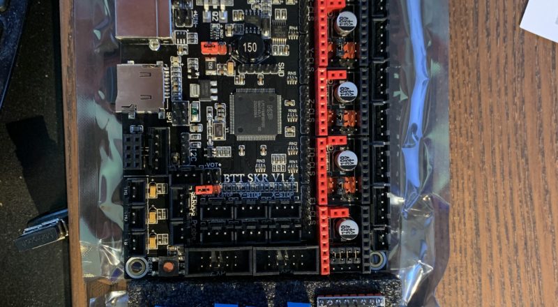
It is very possible to upgrade an Anet kit printer’s motherboard to a BigTreeTech SKR 1.4 with TMC 2209 or similar stepper drivers. In fact- I recommend it as the reduction in noise alone makes it worth the upgrade.
That said- it’s not necessarily “easy”. I’d rate it moderately difficult IF you are good at reworking/crimping JST and Dupont connectors and are comfortable digging-in to Marlin code. You have to re-do several connections because the pinouts are different, and there are a lot of options to set and tweak in Marlin.
I was unable to get the printer’s stock display to work, after more than a dozen attempts from at least that many “How To” posts and YouTube videos online. It’s possible one of them fried something in it. Some people do claim to have made it work, but I’m dubious. It’s also possible Anet or BTT changed something since the HowTos were made (some were a few years old), that further disrupted things.
The alternative was to install a BigTreeTech TFT display. That also doesn’t work as-expected. It won’t work at all in it’s “touch screen” mode with a modern interface. I spent over a week working with their support on it, and came to the conclusion that it just doesn’t work. They claim it is because I am using Octoprint, which causes serial conflicts. I’m not giving up Octoprint for their display, so I just use it in “LCD12864” mode, which emulates the “old” display.
Marlin switched from using/supporting Arduino IDE to Visual Studio Code (yes- THAT Visual Studio, but the open-source version). I still hate it, but am getting a bit more familiar with it now. I’d been using Arduino IDE for a number of years, and still use it for my other microcontrollers.
It took a lot of tweaking and recalibrating to get decent prints again.
There are a lot of “How Tos” online, and I can’t really do the process justice here. It just takes a lot of work.
On the plus side:
The printer is so quiet I sometimes forget it is running. The only real noise comes from the cooling fans now. There are three more- as I added cooling for the TMC 2209 stepper drivers AND the Z stepper motors, which now get quite hot.
The extra memory in the SKR card and a bit of tweaking lets me drive the two Z motors separately. Combined with my auto-bed-leveling probe- I don’t have to touch the Z gantry anymore- there is a Z-Auto-Sync option in Marlin that levels it automatically.
The SKR card has power fail/restart and PSU control options that weren’t available on the Anet card. It can also control LED “NeoPixel” lighting and has additional (add-on) options for WiFi and serial communications. You can also remap most data pins on the card (which does make some things a bit easier when configuring). The card itself is very well built, and I don’t even see a need for separate MOSFETs for hot end and heat bed.
This is probably the best HowTo I found for configuring the new board:
https://3dwork.io/en/complete-guide-skr-v1-4-and-tmc2209
I am NOT using the “sensorless” homing. I don’t really see the appeal to having your X and Y carriages slamming into their physical limits so the steppers start skipping just to home the head. The limit switches work just fine.
This does a nice job of covering the rewiring necessary to make it work with the original ANET hardware. As I noted earlier- I was unable to get the original LCD to work, including by following the instructions in the link.
https://caggius.wordpress.com/anet-a8-rewiring-for-skr1-3/
Here are a few pictures…

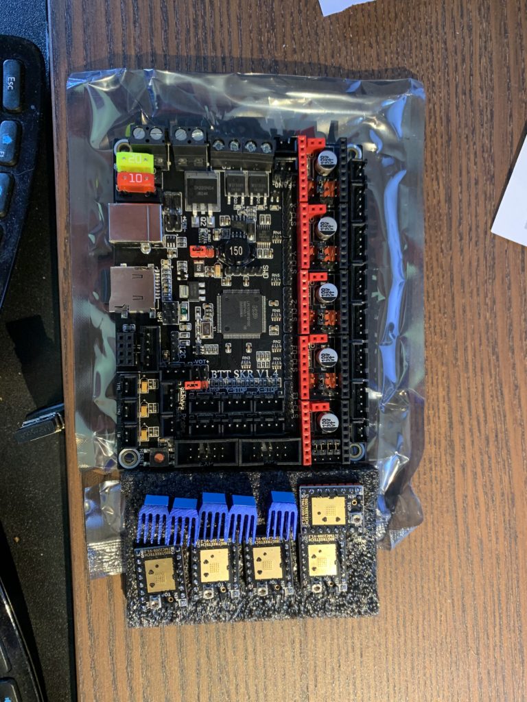
SKR 1.4 Board and TMC2209s, as-received. TMC2209
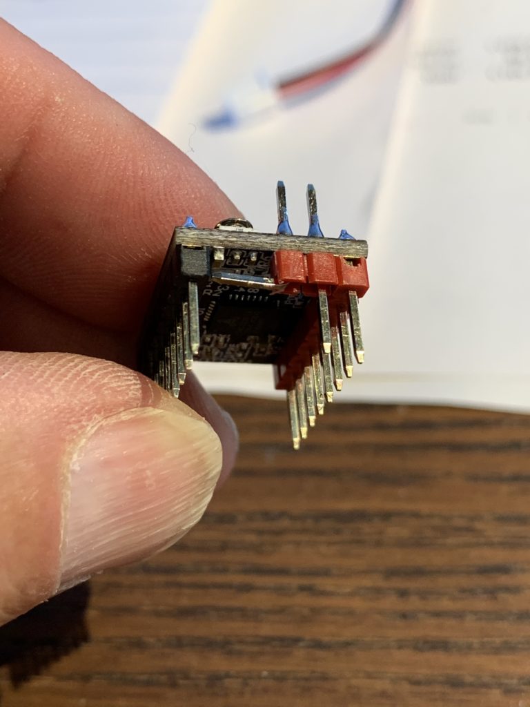
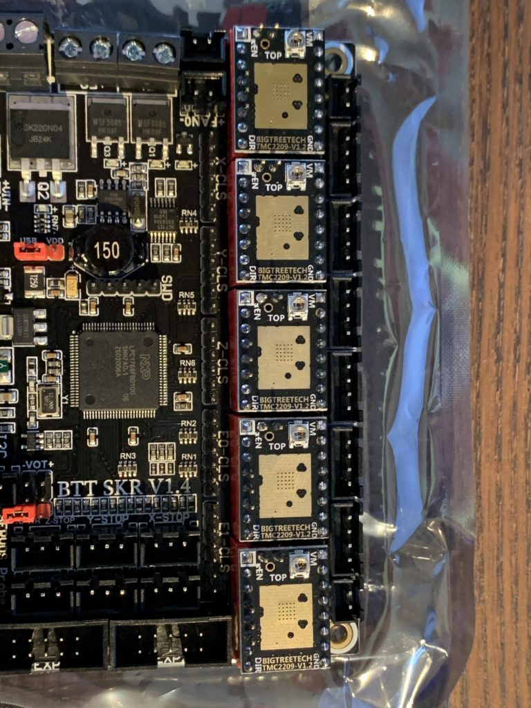
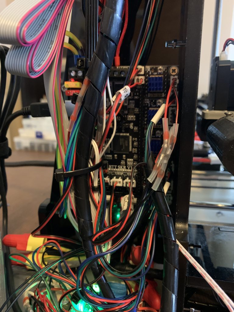
Have to bend the Diag pin to use endstop switches!Jumpers for TMC 2209 TMC 2209s Installed
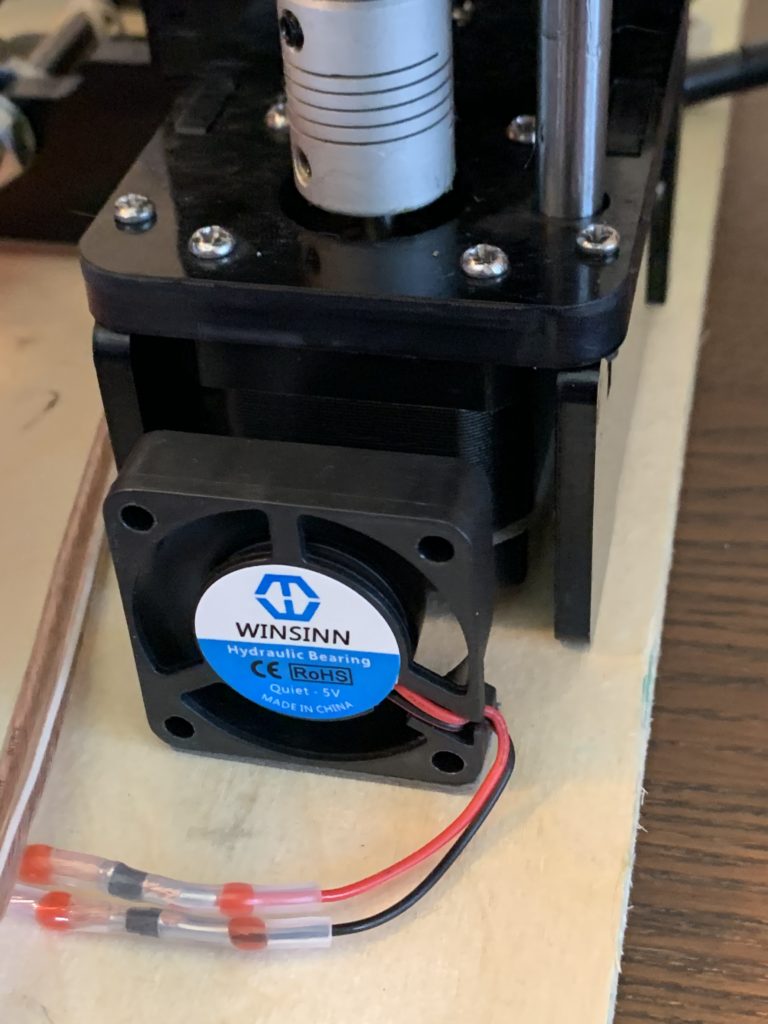
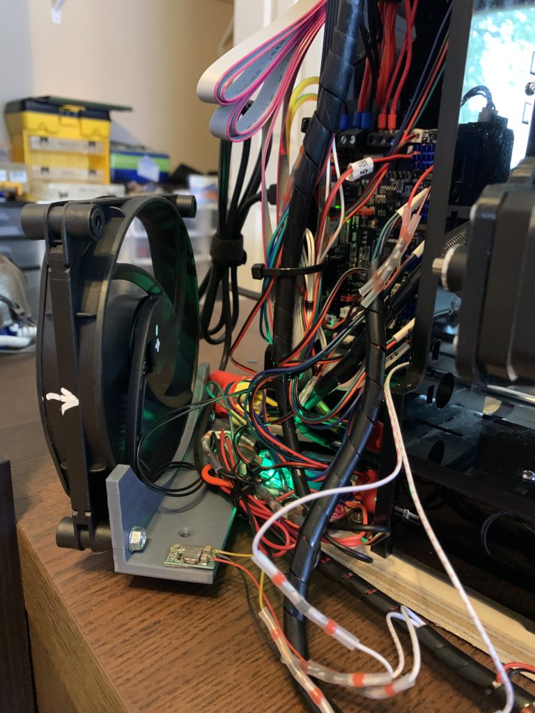
Using for ALL motors. Using E1 for Z2.Had to mount some cooling fans for Z steppers. Completed install. Not pretty but works! Not the best implementation of a cooling fan, but I had the fan “in stock”. Note the little buck converter stuck to the fan mount is for the 5v Z stepper cooling fans (also recycled). 
New hot end with round heater Completed printer, after latest modifications.

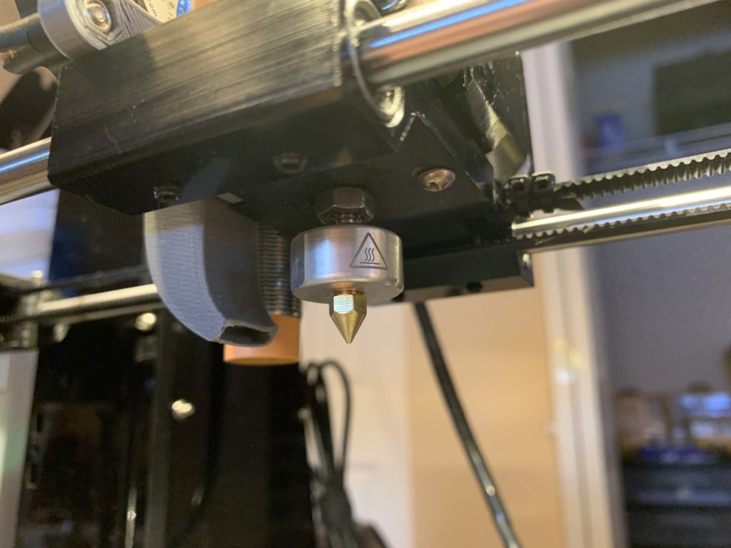
Since I had hot-end issues, I haven’t put wire management back on the wires between the print “head” and the controller.
I also printed new left and right Z gantry sections, and there are new bearings and belts all-around.
Just for more information:
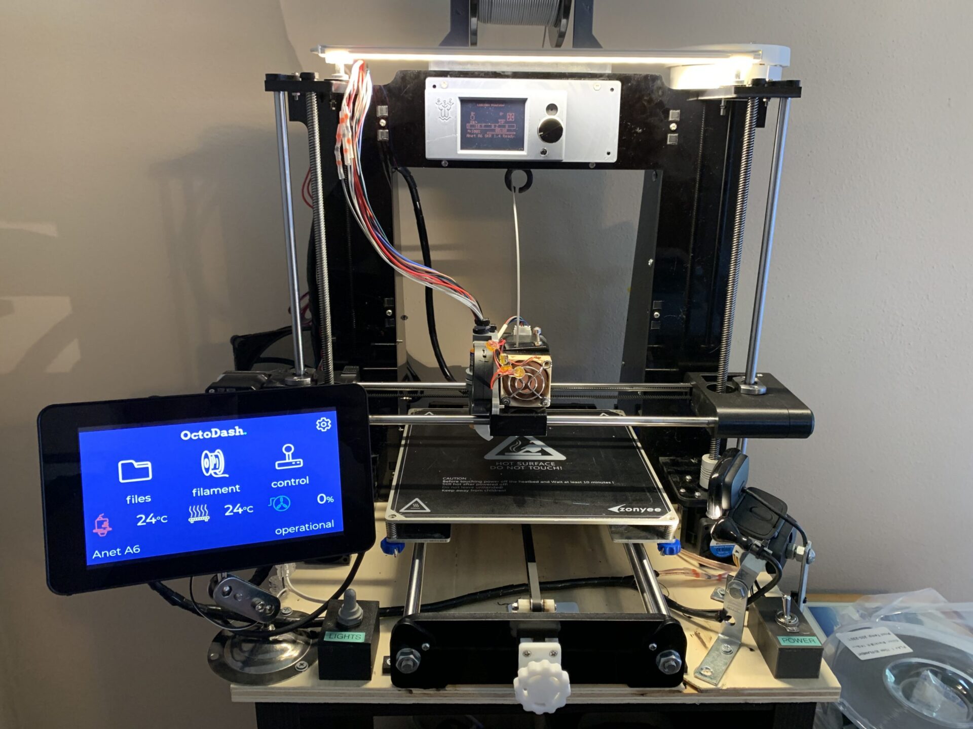
The touch screen on the left is an “official” Raspberry Pi touchscreen. There is an RPi mounted behind it that runs OctoPrint, which controls most of the printer operations. The touch interface itself is OctoDash, which provides an independent front-end to OctoPrint.
The Raspberry Pi is set up to control the printer’s PSU (the RPi has its own PSU) and the lights (light bar on top, and light next to the Webcam on the right) via GPIOs. Just touching the screen turns the printer on, or it can be turned on or off in the OctoPrint Web interface. Lights can be independently controlled via software or the big momentary toggle switch under the screen. The big “Power” toggle switch in the lower-right corner just turns the Raspberry Pi on or off.
The display on the top emulates the original ANET display. I had to print a cover to cover up the old holes for the “factory” one, which no-longer works.
The Z gantry (x-axis) is auto-leveling as the two stepper motors are independently controlled. The heated bed is also auto-leveling using a 5×5 grid. I use an inductive sensor for level detection.
I use a top-mounted spool holder for filament to save space. There is also a smoke alarm mounted to the top of the printer for added safety. My plan is to eventually set up a “wired” smoke alarm to automatically kill the power if there is smoke. The new board and Marlin firmware make the printer significantly safer to run, but because of the high temperatures involved- there is always some risk of a failure causing a fire.
Future:
I printed the parts to convert to an E3D V6 All-Metal style with a Bowden extruder. The more I’ve read though- I don’t feel this is a worthwhile upgrade. Direct extruders just work better, and while the mass of the hot end/head is much higher with the current setup- I won’t gain significant printing speed or quality improvements by switching to Bowden. One thing I may look at is a smaller/lighter stepper motor for the extruder. I did find some good STLs for a direct-extruder E3D V6 setup, but it’s just massive (high) because of the added height of the V6 hotend.
I want to work on cooling the steppers, especially the Z ones, better than the current setup. I’m thinking of mounting the printer on a vented metal shelf so there is better air circulation, and adding heat sinks for the X and Y steppers. The extruder stepper actually doesn’t seem to get all that hot, and I don’t want to add more weight to the head.
I’d eventually like to come up with a better way of mounting the big 140mm board/stepper driver cooling fan. It works as-is, but just looks tacky. If I mount the printer to wire shelves- I may just mount a couple of them underneath it for the board AND steppers.
I want to re-do the power wiring too. There are additional power wires that went to the old bed and heater MOSFETs that I’m no longer using that I need to pull. Right now they are just capped off with wire nuts. (You can see them in the pictures above.) I have to pull the PSUs off the frame to disconnect them. I would also like to replace the noisy conventional opto-isolated power relays I am using with SSRs, and mount them in a nice way. You can see part of one of the current relay modules under the mainboard.
I may also be using it less anyway. I’m venturing into the world of “SLA” Resin printing. Just waiting for the new printer to arrive from China. I’ll post more about that once I get set up. 😊