MAX485 Differential Transceivers
I was digging into how Differential Receivers for LED lighting systems work, and was told about these MAX485 Transceivers on one of the forums:
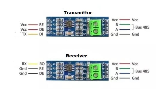
These little boards cost around $1 each, and can be used to extend a WS2811 (Pixel) data signal for hundreds of feet (probably close to 1000 with proper shielded RS-485 cable). You don’t have to use the Differential ports on your controller- you can extend any pixel port.
My understanding is that the 4-Port differential systems used on Falcon and Kulp boards use similar technology- the transmitter side is built-in to the boards, and they use all four twisted pairs in a Cat. 5e/Cat. 6 cable, with RJ-45 jacks to make it easy to connect. The Smart Differential Receiver boards just use the networking capabilities built-in to the RS-485 standard.
I like the idea of using these for one-off props or strings that I don’t want to waste a “real” 4-port receiver board (and port) on. For example- I have a “Tune To” Matrix that is on the other side of my yard from my display. I plan to run it wirelessly now, but could use this for it.
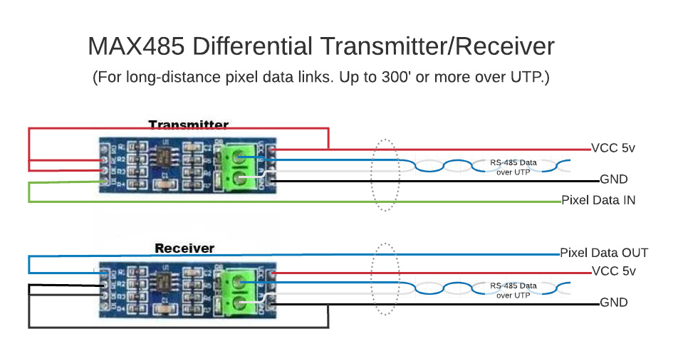
The pins and picture are a bit confusing until you dig into the workings of the MAX485 board. RE and DE enable/disable the transmit or receive function of the board. By setting RE and DE high (by applying 5v, Vcc), you enable the transmitter function and disable the receiver. By setting them low (Gnd), you disable the transmitter and enable the receiver.
You need to provide 5v Vcc and Gnd anyway on the right-side pins (in the picture). The board is set up to use 5v logic level control to switch modes between transmit/receive as needed. We are only using them one-way, and don’t need an MCU or other controller- we can just use Vcc/Gnd to provide the control logic it is looking for.
The A & B ports send/receive RS-485 Differential Serial Data. This is “2-wire” data that does not reference or use Gnd. It can travel long distances and is commonly used in process control, laboratory equipment, alarm systems, and for simple “networks” of serial devices like POS terminals to card readers, check printers, etc. The two larger screw terminals are connected to the two A & B pins/solder pads- so either can be used.
RS-485 data usually uses a single twisted pair in a ground-shielded cable. The ground-shield protects the data from outside interference and allows for very-long travel distances, but is NOT a component of the data signal itself, and is not needed for shorter runs. Because of this- ANY UTP (or STP) cable can be used. I’m just going to use good ol’ Cat. 5e Ethernet cable.
Real commercial RS-485 installations actually use a 3rd Ground connection as part of the cable. This is to help insure ground continuity between devices. It has nothing to do with the actual RS-485 signal, and for our purposes- is unnecessary. The grounded cable shield is generally ONLY grounded on one end, and is not used to prevent any ground potential issues.
Okay, so I decided to draw up my own wiring diagram for all of this, just so I knew what I had to do when I started building my transmitter and receiver:
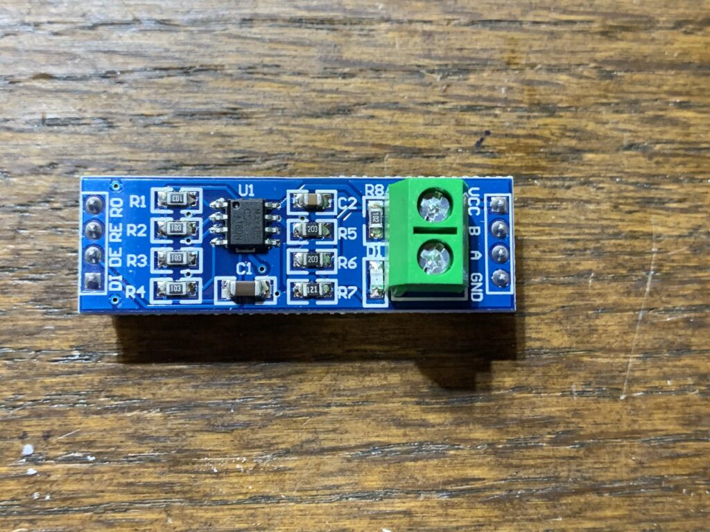
I ordered 10 MAX485 boards on Amazon for a little over $10. They actually look identical to the pictures, even though I saw several “manufacturers” of them. I’m pretty certain they adhere to a common form-factor so they can be replaced easily in commercial systems.
Like most of my builds- I decided to put these into custom 3D printed plastic boxes that I could seal up so they can be used anywhere. Also, like most of my recent builds, I decided to use “Dupont” connector jumper wires to actually hook it up. They only seem to come with pin headers already soldered to them, and I don’t like soldering to pins. (I may just need to start doing it anyway, as the connectors are kind of a pain to work with too.
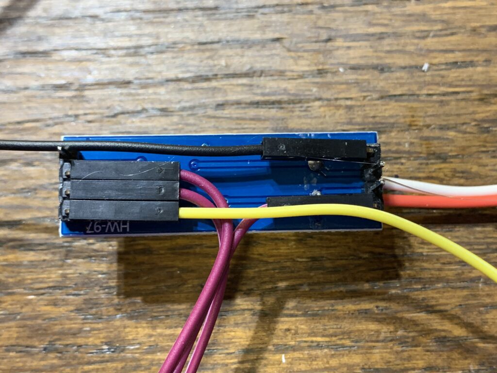
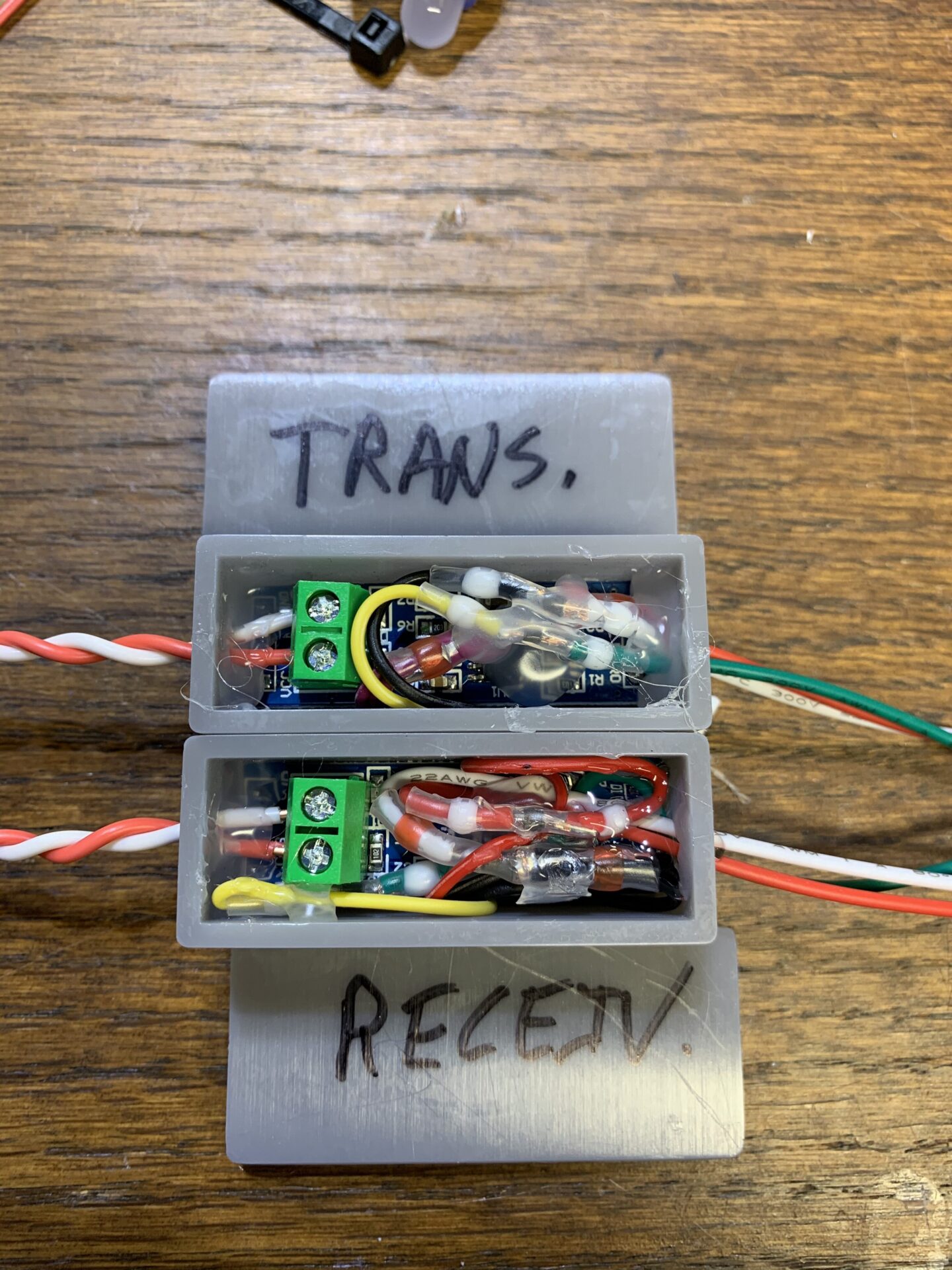
So here is the Transmitter with wires connected and pins folded into the bottom to save space. As usual I hot-glued them underneath to stabilize them and keep them from coming out. The purple wires are Vcc, black is Gnd and yellow is data-in. The larger red and black wires are RS-485 data, out in this case.
I then stuffed it into its little box, running the RS-485 wires out one end. I used a JST connector for data/power in the other end of the box. I hooked it up using solder-seal connectors…
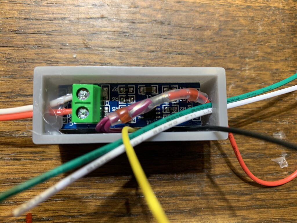
I had to use a red solder-seal for the Vcc wires, and there wasn’t enough room for it in the little box. I snipped it down close to the red sealant rings so it would fit. Then I hooked up Gnd and Data using the much smaller white solder-seals.
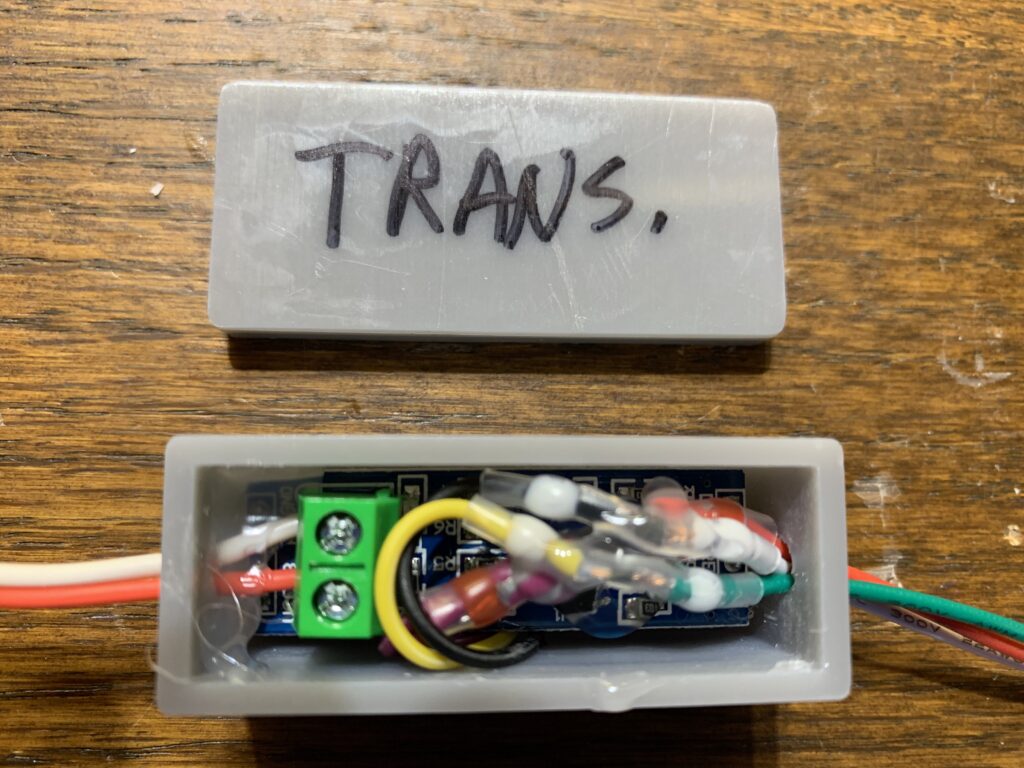
I used copious amounts of hot-melt inside the wire holds, and to immobilize the solder-seals and keep everything relatively-neat inside the box.
I build the Receiver similarly…
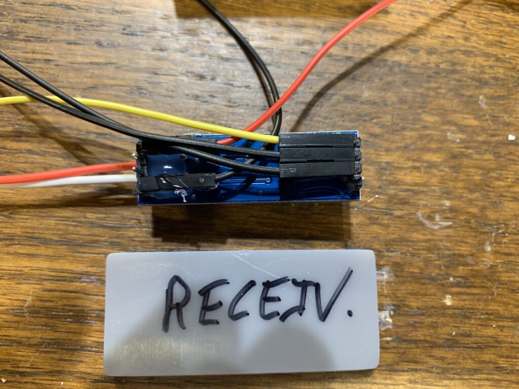
This picture is flipped from the Transmitter one, but note the 3 ground wires and single Vcc wire now, and shifted pin positions.
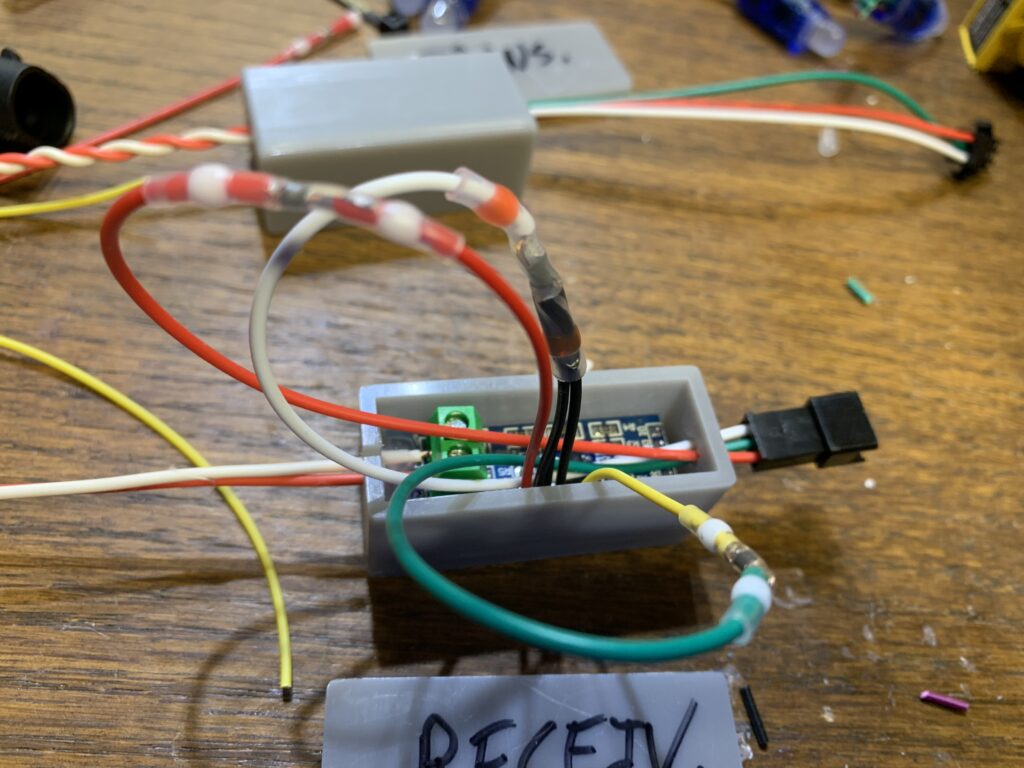
This shows a bit more detail of the top wiring. Again I cut-down the red solder seal so it is only slightly longer than the white ones.
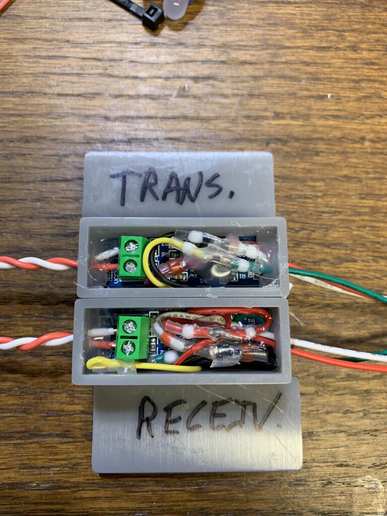
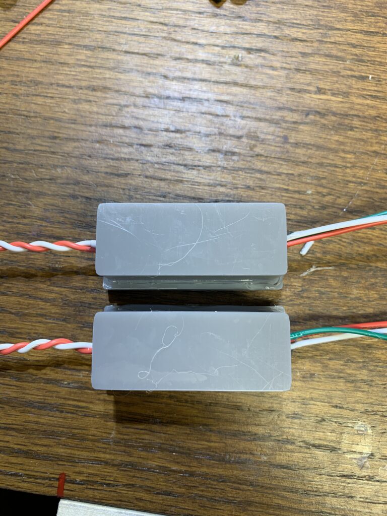
I sealed the tops onto the boxes with more hot-melt, along with both wire ends. Then I drenched them thoroughly in Flex-Seal and hung them up overnight to dry.
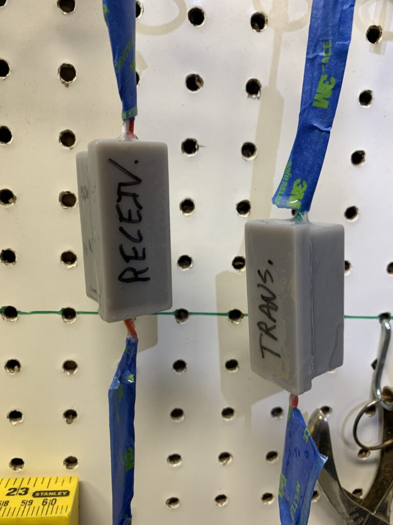
TO BE CONTINUED…
That’s it for the build. I’m hoping to get time to test these this weekend, as I will be putting more props out. (The controller is outside and it’s been raining for a week now.) My plan is to hook these up to either end of a box of Cat. 5E cable that has about 350′ of cable left in it, and see if I can get data to a prop with them.
One thing I did not accommodate in my build is termination. In RS-485- the last device in a “network” needs to be terminated for data integrity. I don’t know if it is strictly necessary with these transceivers in a point-to-point configuration like this. In all of the usage examples I found for them online- termination is not used unless multiple devices are used in a network. If I have data issues- I will add a terminating resistor to the receiver.
Also- my plan for using Cat. 5e UTP is to use the Orange pair for differential data (White/Orange = A, Orange = B) and ground the rest of the pairs on the controller side. The latter isn’t strictly necessary, but it may help shield the data conductors without using STP cable.
