More Power!

So the front of our house has a bunch of convenient outlets, but they are all run off the same 15A GFCI breaker. Knowing that likely wasn’t going to be enough power for our show, we ran quite a bit of our 2020 show using extension cords from a set of 20A outlets we have in the back of the house. This obviously wasn’t very convenient or probably safe. Each extension cord also had a relay box on it, which worked well, but provided multiple potential failure points.
This year I wanted to have dedicated outlets just for the show in front of the house. I also wanted to eliminate all (or most) of the little relay boxes we used to power the show on and off. Since the pixels and controllers all use power even when they are “off”, I actually want to cut the power to them when our light show isn’t running.
Starting in 2021- my control boards and pixels are all powered separately. The Raspberry Pi and BBB SBCs (controller computers) will stay on all the time so I can update and test them during the day. The controller boards themselves, differential receivers, matrixes, and all pixel strings are only powered (using this system) while the show is active. This is for safety and energy savings.
So, I installed two dedicated 20A outlets in front of the house, along with a power management and monitoring system for them.
UPDATE (November, 2021):
My intent was to keep the controllers powered up all the time and only power the pixels on using this setup, but it doesn’t work. I believe if the controllers are powered up, even if by a separate supply, they attempt to send power out to the pixels via the capes. None of them would boot consistently without having the pixels energized. If they did boot- they often wouldn’t connect to the cape when it was powered up. At this point I honestly don’t understand why separate power is even an option for these controller capes. I’m currently only using Kulp controllers (A K16, K40, and four PocketScrollers), so this may be different for Falcon, Hanson, or Hinx controllers.
So for now- I’m just powering up the whole show when I want to install updates or load new sequences during the day, and then shut it down when I am done. Next year I might pursue trying to switch the DC just to the pixels using MOSFETs, so I can keep the capes powered.
UPDATE (January, 2022):
The system worked flawlessly for our show in 2021. The SSRs were quiet and didn’t even get noticeably warm. While I anticipated a much higher load based on PSU ratings, and spec-ed for it accordingly, neither circuit exceeded 4A during the show’s operation! It is safe to say that this build exceeded my expectations.
The ONLY issue we had was the GFCI outlets I installed seem to be overly-sensitive and we had a lot of nuisance trips. I’m going to try installing a different GFCI brand for testing over the Summer. We had them trip randomly in perfectly dry conditions, and with specific hardware like brand-new PSUs and differential receivers (that do not trip other GFCI outlets or breakers in the house). I have the same model GFCI in another location inside the house and confirmed that specific components would trip it, while not tripping others, so I believe this is a manufacturer issue. I may also switch to either GFCI breakers or another internal option as I often had to reset them in less-than-ideal conditions outside.
UPDATE (October, 2023):
If you buy a new controller, chances are it will have e-fuses in it and you can toggle the pixels on and off without powering down the controller board. It seems like all of the popular vendors are jumping on this bandwagon. So, at least if you buy new controller, you actually can control the pixel power separately!
While we ran our show for two previous seasons on this system with no obvious issues, I found out something while starting setup for our 2023 show. There is a big problem using SSRs for something like this, which may explain some SD card and other random shutdowns and failures I’ve had over the last few years. Scroll down to the bottom for more information.
Power Controller Project:
This was originally written for an earlier version of this controller with both SSRs triggered by a single GPIO. There were several issues with it, including issues with the DIN enclosure I was using and concerns about the heat generated by the SSRs. I abandoned it and re-grouped for this revised project. There are still some references to the original project below…
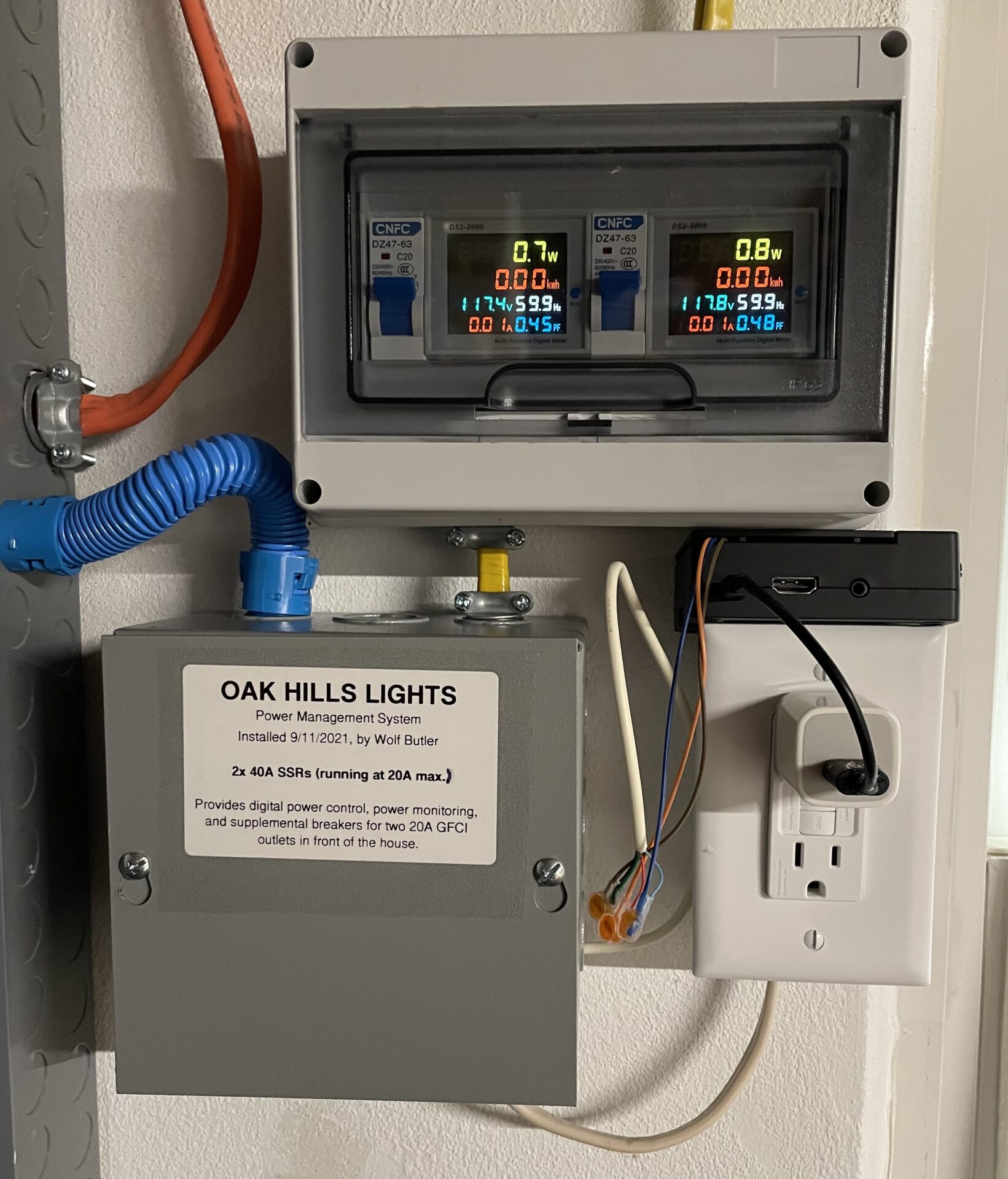
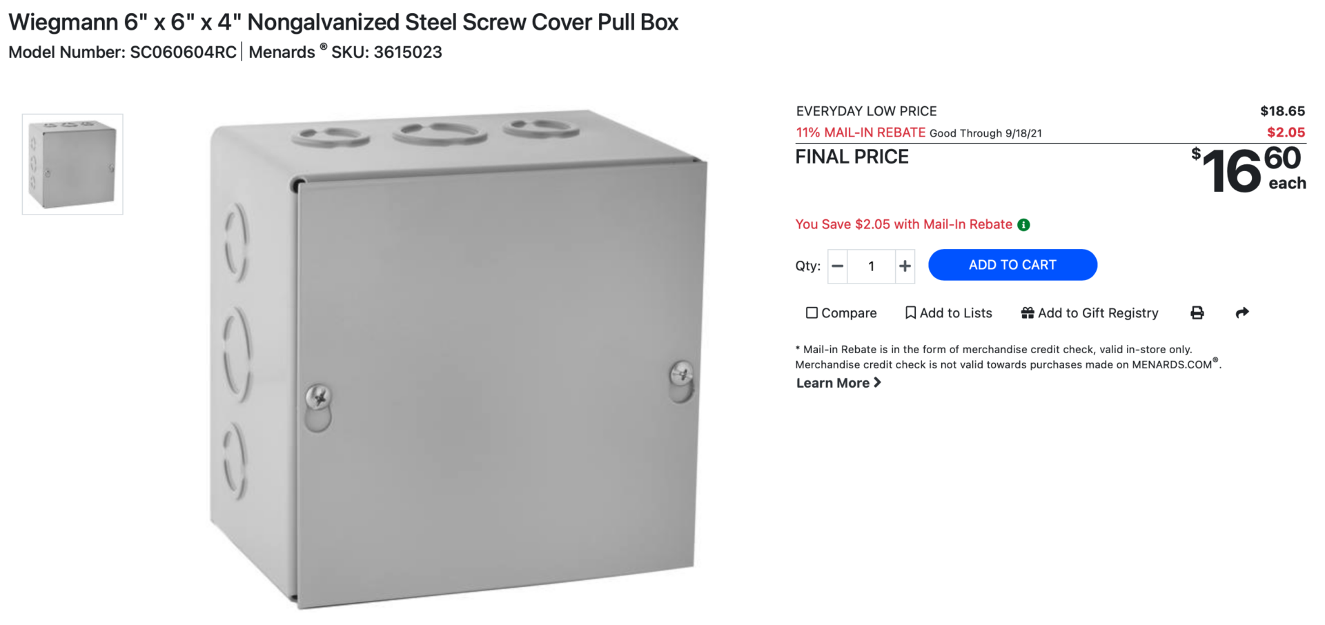
First, I found an “8-Way” DIN rail box with an actual clear cover that fits the power monitors and the new breakers. Here is the box and breakers that I bought:
I also found a larger metal junction/utility box to put the SSRs in. I got it from Menards, but they should be available at about any home center.
I mounted the SSRs in the metal box. I also hooked up an outlet to power my Raspeberry Pi, or anything else, since there wasn’t an outlet in that corner of the room anyway. It’s a GFCI since it is near a laundry tub in an unfinished section of the basement. This outlet is not switched by the SSRs. I am using thermostat wire to separately (now) drive the two SSRs from the Raspberry Pi.


I then routed the power up to the new DIN rail box, which contains the power monitors and supplemental breakers. The neutrals and grounds run through to the outlets outside. The hot leads run through the power monitor’s inductive pickups, and then through the breakers before heading out to the outlets. The power monitors also have hot and neutral leads for their own power and voltage/Hz monitoring.


This makes for a much cleaner and safer install. The SSRs are safely enclosed in a metal container in case they fail, and also to provide much better heat conduction. Once I have them loaded, if they do seem to get too hot- I may add vents and a cooling fan. I’m not expecting them to get too hot since I over-spec-ed them at 40A each. If they get really hot- I may swap them out for contactors instead.


The outlets and power monitors are only energized if the SSRs and supplemental breakers are on, so I have a quick indication of the system status. If the power monitors are on- the outdoor outlets (and main show power) are on. If one or both are off, and a power trigger has been sent- something is wrong. An overload should trip the supplemental breakers first, saving the SSRs, otherwise everything is still on 20A breakers in the main box. Of course the outside outlets are GFCI-ed as-well.
The Raspberry Pi and logic-level converter board are in the small case on top of the outlet box. I have it hooked up to the show network via Ethernet now, as I just don’t trust WIFI for this stuff. I also have each SSR controlled separately now as-well, so I’m using two GPIOs (more info about this below). Here is a diagram of the data-side from the Pi to Logic Level Converter to the SSRs…
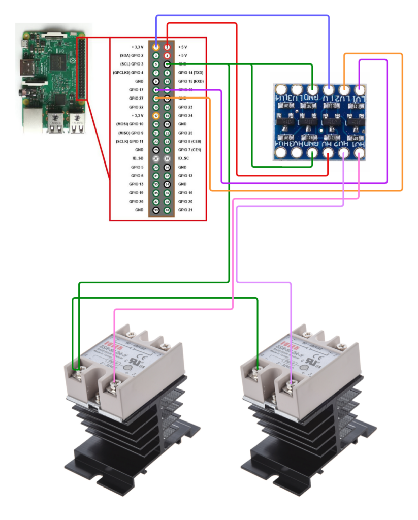
So, the RPi runs FPP (Falcon Pie Player) 5.x in Remote mode. I have it configured to toggle the GPIO on and off using FPP’s built-in GPIO controls and a single-channel Pixel Overlay model. The Overlay Model is independent and can be used via scripts to toggle the GPIO, without having to build it into any sequences. I can incorporate this (and other power management like the FM Transmitter and Projector Power) into my show playlists, toggling the power on just before the show begins, and off when it is done. For now, I decided to just use one GPIO to control both SSRs. In the future, I can easily split them or add more if I want to have finer control of which outlets are on.
The screen grabs below were from an earlier build, which I only used 1 GPIO for. I’m switching the outlets individually now, so I’m also using GPIO 27. I have the outputs named Power-L (GPIO 17) and Power-R (GPIO 27), for the positioning of the outlets.
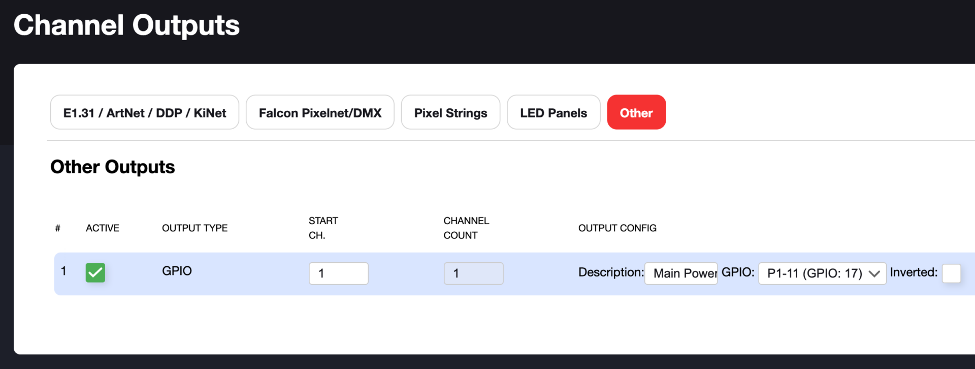
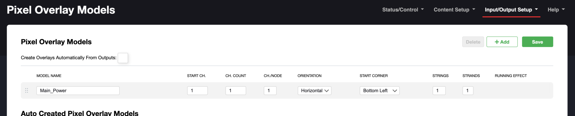
Quick Update (Oct. 2023): There are GPIO-On and GPIO-Off scripts in the FPP script repository. After you assign the Outputs to the GPIOs, you can just edit these scripts to control them directly. You don’t need to worry about pixel overlays.
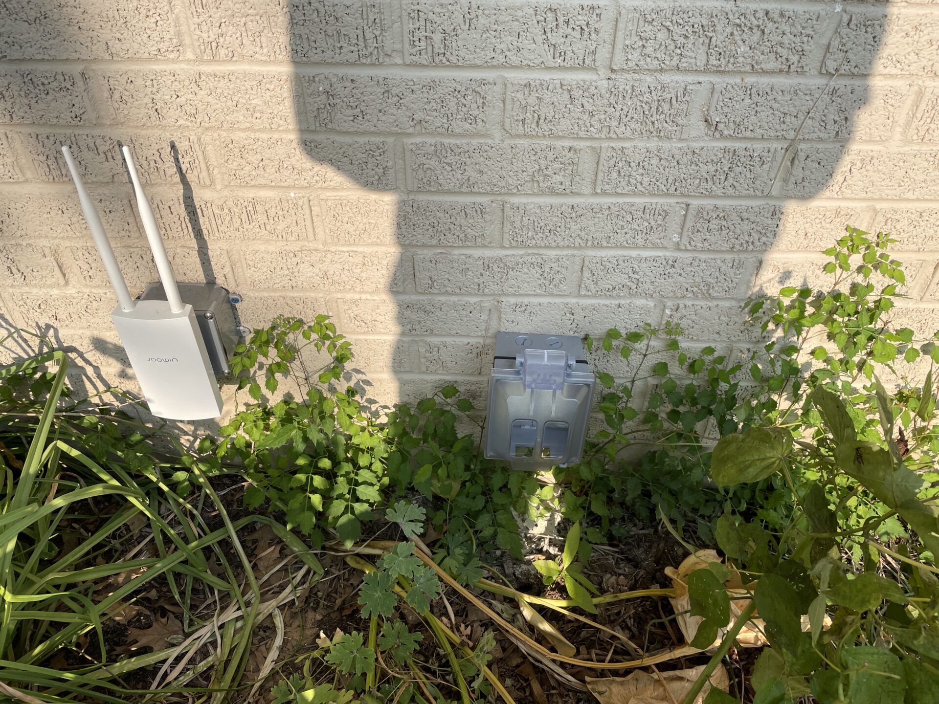
On the other end, I installed 20A GFCI outlets in a weatherproof double-gang box with an in-use cover. These outlets will run all of the differential receivers and pixels. The primary controllers, including the Master controller, will remain on all the time. They use minimal power and I don’t want to have to build-in additional delays to wait for them to boot up. I actually now keep the FPP Master controller running all the time, even during the off-season, as I plan to use it for other lighting projects, and use it to test new FPP versions that come out over the course of a year.
Safety note:
SSRs are never truely OFF. There is a tiny amount (usually around 3mA) of “leakage current” through the circuit when the SSR is not triggered. While this is not enough to be overly dangerous- you should still never consider an SSR-controlled circuit to be “Off” unless the source power is cut completely.
To use a real-world example- I have a small network switch for our show plugged into one of the outlets. The leakage current is enough to actually power it- it stays on all the time, even when the SSRs are “Off”.
Important Update, October 15 2023
I noted in the paragraph above that the SSR leakage current was enough to power a small network switch. Well, I discovered this year doing setup that it can power much more than that. I no-longer have the network on this system, as I want it online all the time, but I do have all of the other controllers, pixels, and projectors on it.
I had installed one of our K40D-PB controllers and was hooking up some of our props to it. I had just checked the controller out last weekend and verified it was working fine. After setting it up to run some of the props with installed over the weekend for a test, I discovered it wouldn’t boot. It appeared the SD card was toast.
I installed FPP on another SD card and plugged it back in on my bench inside to test it again, and all was good. I configured everything and then put it back outside. It was working fine at that point. I had to do some other work so I turned off the power and left it for a few hours. When I came back and turned the power on, as it was getting dark, nothing happened. The SD card was apparently corrupted again.
So, here’s where things got weird. I powered off the system again and began disconnecting everything. I usually don’t connect or disconnect cables while the system is “hot”. I had decided to just leave it in-place and pull the SD card out to replace it with yet another one. When I opened up the box, I was greeted with a very strange site. The PSU, voltmeter, and controller were rapidly flashing on and off. There were two differential receiver boxes doing the exact same thing. This was with the system power turned OFF. It was that darn leakage current! Apparently it was just enough to kick the PSUs on for a split second before they shut down, and the tiny amount of capacitor power left over was enough to start the boards booting!
I figured being rapidly turned on and off probably thousands of times was enough to corrupt the SSD of the Pocket Beagle running the K40D. I probably didn’t notice it before because there were enough other loads connected to each SSR that the leakage current didn’t have a chance of starting anything. Still, I had odd random pixel flashes and other unexplained failures last year that could have been caused by this.
So, long story short, I don’t recommend using SSRs for this application! They seemed like a nice quiet mechanical relay substitute without the possibility of contact or coil failure, but the leakage current could be damaging my controller hardware, so they have to go…
I had some logic level triggered, opto-isolated, 120v 30A relays I bought for another project that were never used, so I decided to quickly replace the SSRs with them. I had to run 5v to them for VCC/running voltage, but otherwise I was able to sort of drop them in-place.
I put several layers of Kapton tape over the high voltage traces and pins on the back of them, and then fastened them using heavy duty hook and loop tape and hot-melt glue to the existing heat sinks. I didn’t want to have to disconnect every thing and remove the box from the wall, so this was the best solution I could come up with. The relays were an odd size, and I couldn’t find a more-suitable mounting option for them in-stock.
Here are a couple of pics from the install:
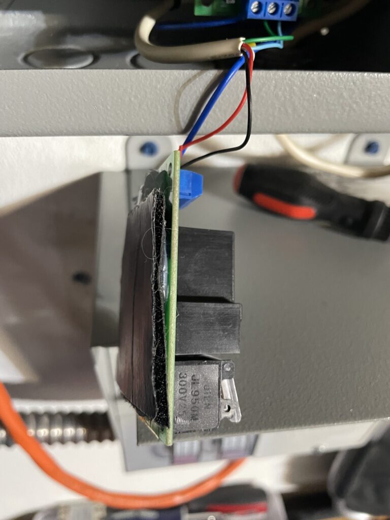
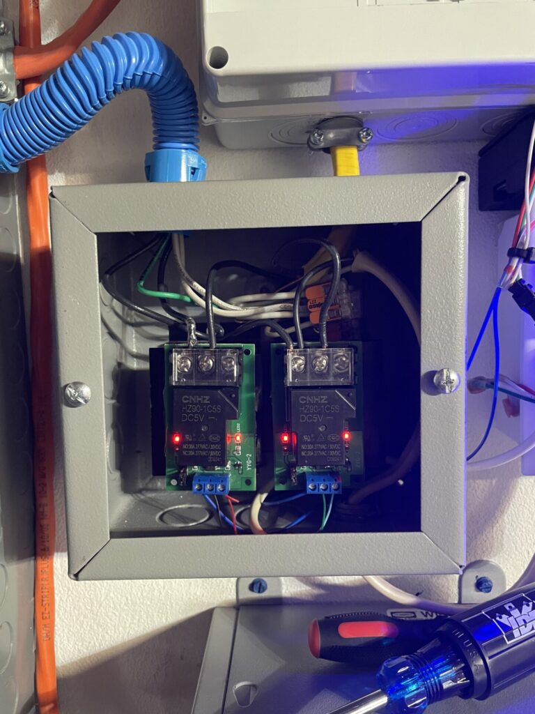
This isn’t as “professional” as my SSR install was, but should hold together for this season. The relays don’t get warm at all, and I’m not really pulling more than 10A through each one. I plan to re-work the whole thing after this year’s show. Even if the adhesive fails, the 120v wire is enough to hold the relays up, and they have shields over the conductors.