
FrankenPower Mk. III
Important Notice
This site is no-longer being maintained, and the content and links found here may be irrelevant and outdated. It is online for archival purposes only.
FrankenPower Mark I-II used mechanical relays that were connected to conventional outlets. They were bulky, probably not very safe, and had to be placed in a tote to try to keep them protected from the weather. One of the original mechanical relays failed almost immediately upon use.
Mark III uses an 8-channel SSR board and a much different enclosure- a “Weatherproof” cord box I found at Menards:

I built it primarily using the following components:
Along with WAGO connectors and cheap 10′ extension cords from Menards. I cut the extension cords in half, and will use the male plug side for PSU builds.
To start, I soldered jumper wires to the D1 Mini in much the same way as I did for FrankenPower Mk. II. This time I connected them to an 8-channel SSR board, instead of mechanical relays.


I connected the 5V and GND pins on the D1 Mini to VCC and GND on the SSR Board, and then connected channels 1-8 of the SSR board to GPIOs 5, 4, 0, 2, 14, 12, 13, 15 on the D1 Mini (the same as before).
Then I loaded the current version of my Node Relay Controller x8 software on the D1 Mini. This is the same as the most-recent revision on the FrankenPower V2 build. I’m using DHCP with Multicast for this particular build, and future relay builds:
/* Modification of old E1.31 single-channel relay controller
 * Supports 8 channels from the starting universe selected.
 * By Wolf Butler
 */

#include <ESP8266WiFi.h> // a library to include
#include <E131.h> // a library to include https://github.com/forkineye/E131

//Set your WiFi network information below...
const char* ssid = "My_WIFI_SSID"; // your network AP SSID
const char* password = "My_WIFI_Password"; // your network AP password

// Comment the following out if using DHCP, otherwise- adjust as-needed.
// Important: Those are commas, not periods!!! This is just the way the IPAddress datatype works.
//const IPAddress ip(10,0,0,251);
//const IPAddress netmask(255,255,255,0);
//const IPAddress gateway( 10,0,0,1);
//const IPAddress dns(8,8,8,8);

//See below to set Multicast or Unicast. Default is unicast (TCP).

//Set the universe and START channel you want to use. Universe is E1.31 (DMX) universe.
//Generally you will just use 1-8, so just leave the default of 1.
const int universe = 1; // universe to listen to

//Generally you want consecutive channels starting at 0 (which will be 1 in the controller/control software).
//This MUST match the number of outputs below or bad things will happen.
int channels[] = { 20, 21, 22, 23, 24, 25, 26, 27 };

//Set the output pins here. These are the GPIO pins, and not necessearily "D" pins.
//For example- for the D1 Mini, pin GPIO 5 is "D1". We would enter pin 5 in this case.
//In short- "D" numbers don't correspond to GPIO numbers.

//Example: For D1, D2, D3, D4, D5, D6, D7, D8 on the D1 Mini, use..
//int outputs[] = { 5, 4, 0, 2, 14, 12, 13, 15 }

int outputs[] = { 5, 4, 0, 2, 14, 12, 13, 15 };

//Don't mess with these...
int channel_val; // the current value of the channel we are using, don't change this.
long int num_ch_in_pkt; // number of channels in the recieved packet, don't change this.
E131 e131;
int cval[8]; //Used for formatted output to serial terminal

void setup() {
  Serial.begin(115200);
  Serial.print("Connecting to ");
  Serial.println(ssid);

  //If you want to use DHCP instead of a fixed IP address (above), comment the following line out...
  // WiFi.config(ip, dns, gateway, netmask);

  WiFi.begin(ssid, password);
  while (WiFi.status() != WL_CONNECTED) {
    //Loop (forever) until WiFi is connected.
    delay(500);
    Serial.print(".");
  }

  //Initialize the GPIOs and set the relays to off (default- Low)
  for ( int i = 0; i < 8; i++ ) {
    pinMode(outputs[i], OUTPUT);
    digitalWrite(outputs[i], LOW);
  }

  // **** Pick one. You can either use Unicast or Multicast. If you don't know which- pick Unicast. ****
//  e131.begin(E131_UNICAST, universe);   //Unicast (TCP)
  e131.begin(E131_MULTICAST, universe); //Multicast (UDP)

  Serial.println("Waiting for channel data...");
}

//Don't change anything below...
//Any DMX value under 127 is "Off", above 127 is "On".

void loop() {
    /* Parse a packet */
    uint16_t num_channels = e131.parsePacket();

    /* Process channel data if we have it */
    if (num_channels) {
      Serial.printf("\nUniverse %u / %u Channels | Packet#: %u / Errors: %u\n",
      e131.universe,              // The Universe for this packet
      num_channels,               // Number of channels in this packet
      e131.stats.num_packets,     // Packet counter
      e131.stats.packet_errors);   // Packet error counter
      for ( int i = 0; i < 8; i++ ) {
        channel_val = e131.data[channels[i]];
        cval[i] = channel_val;
        if (channel_val > 127) {
          digitalWrite(outputs[i], HIGH); // SSR on
        }
        else {
          digitalWrite(outputs[i], LOW); // SSR off
        }
      }
      Serial.printf("GPIO:Channel Values:\t%u:%u\t%u:%u\t%u:%u\t%u:%u\t%u:%u\t%u:%u\t%u:%u\t%u:%u\n",
      outputs[0], cval[0], outputs[1], cval[1], outputs[2], cval[2], outputs[3], cval[3],
      outputs[4], cval[4], outputs[5], cval[5], outputs[6], cval[6], outputs[7], cval[7]);
    }
}
After loading, I powered up and tested the SSR using xLights. I just sent a test pattern to the Universe/channels and observed the LEDs on the SSR board (as seen in the pictures above).
Once I verified that both the software and hardware were working, I started assembling it into something I could use outside to control the power of “dumb” lights and other props.

Initial Hardware Mounting
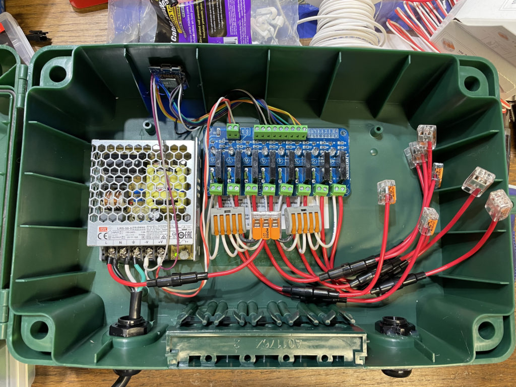
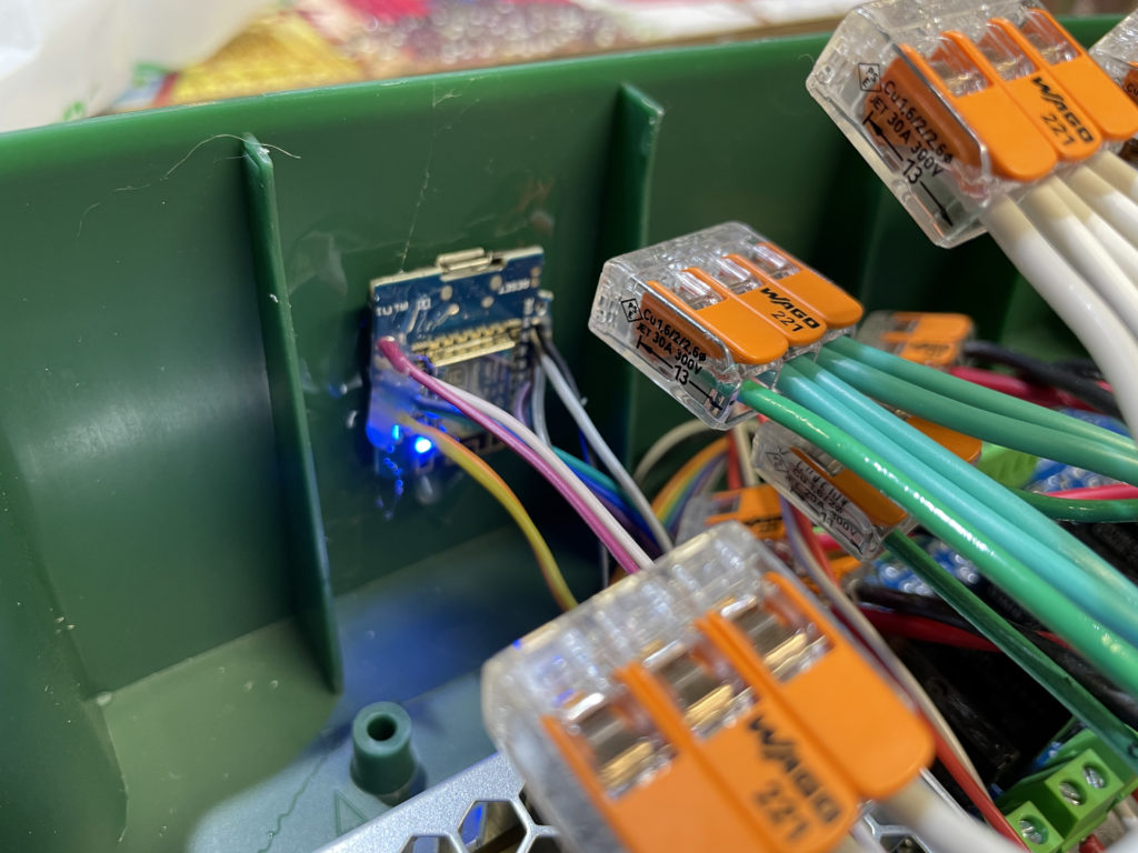
The box came with some strong double-sided hook-and-loop tape, so I used it to mount the PSU and SSR boards inside the box. I also used some hot-melt under the SSR board is it was pretty uneven. I used nano/”Alien” tape and hot-melt glue to mount the D1 Mini to the top side of the case for hopefully optimum WIFI reception. While not show in this picture, I also connected a tiny voltage meter that is mounted to the left of the PSU. This allows me to quickly verify that the PSU is working properly. You can see in in later pics below.
I used a spare heavy-duty power cord to run 120v AC to the PSU and SSR board. Since I’m not using USB to power the D1 Mini- I have power from the 5v PSU going directly to the 5v and GND pins on it, and the VCC and GND pins on the SSR board.
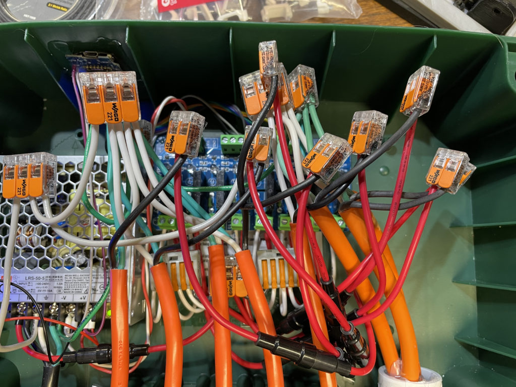
Here you can also see that I have fuses on everything- 15A on the inputs, and 2A on each output channel. There wasn’t really room or a way to connect bus bars to the inside fo the case, so I’m taking advantage of several 2, 3, and 5-port WAGOs for AC power. I will admit the picture above is a bit confusing. I used surplus silicone-jacketed 16ga stranded chassis wire to connect the SSRs to Hot, and those wires are white.
You can see everything connected up in the next couple of pics. Ground and Neutral leads are connected together, and the fused hot leads from each SSR are connected to their corresponding cord. Note that the SSR board is upside down in this install, so the channels are reversed. This made the wiring a bit messier.
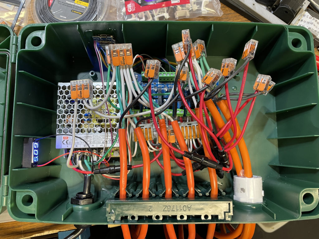
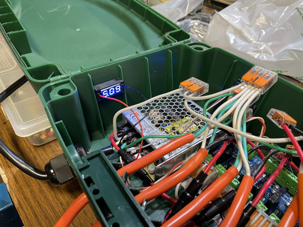
I’m installing these little voltmeters in all of my PSU, Controller, and Differential Receiver boxes. They are cheap, and a very quick way to verify power if debugging an issue. They do have a little potentiometer that allows you to calibrate them, and I did have to adjust a few of them. I 3D printed little boxes for them and just potted them in with electronics RTV. They can be mounted with 3M HD double-sided tape, Nano/Alien tape, or good old hot melt glue.
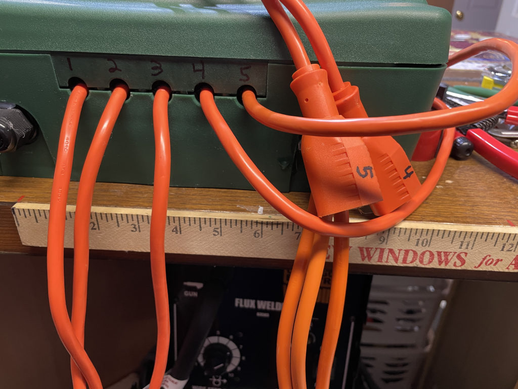
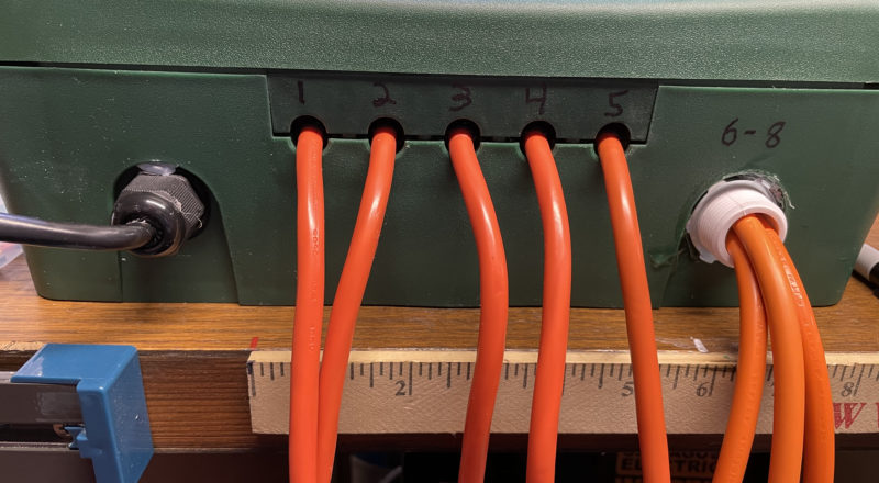
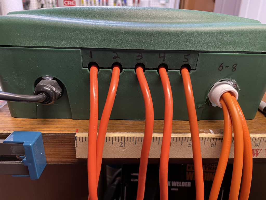
Once I had everything connected up- I closed up the box and labeled the outputs and output cords. I then did one more verification to make sure everything was working as-expected.
And finally, a quick label:
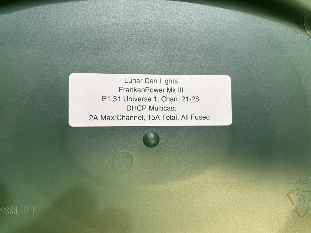
And that’s it. It was actually a pretty quick build, and now I have something I can just hang off of a board, wall, or PVC pipe out in the yard, and can control the power for 8 props.
One thing I didn’t note for the earlier D1 Mini build- channels 3 and 4 do flash on briefly during boot-up. This is fairly common for GPIOs on micro-controllers and SBCs. They are barely on long enough to be noticeable, but still you should be aware of it.
The earlier FrankenPower iterations used 10A relays, so could have switched more power, but given that they only had a 15A input- they would have never been able to work with that much power anyway. The SSRs used here are only good for 2A each, but for powering wireframes, blowmolds, inflatables, and “dumb” LED lights- that’s more than sufficient.
I do have some 20A contactors and plan to get some single-channel SSRs, so I could make some high-current switches as-well if I need to. Those will be documented as another project if I do. 😊