Changes/New Controllers
Important Notice
This site is no-longer being maintained, and the content and links found here may be irrelevant and outdated. It is online for archival purposes only.
After some experimentation with my combined PSU/Control box plan, and after taking a serious look at the cost of PSUs and pixels, I decided to make a few changes…
First- it just isn’t practical to have a separate PSU for every string of pixels. It would just be too expensive since high-wattage PSUs are significantly cheaper/watt. It would cost 2-3x as much just for the PSUs for my original plan.
Second- it will be a lot easier, safer, and more-reliable to place the PSUs where they can be easily accessed, as opposed to trying to place them securely on the roof, for example. Wire just isn’t THAT expensive.
One other big change I’m making is switching to 5v pixels. The main roof line will be 12v, mostly because I’ve already invested in those, but paying a premium for 12v pixels just to save a few power injection splices doesn’t make any sense. I’ve found 5v pixels as much as 40% cheaper than 12v ones, and the PSUs are slightly (around 10%) cheaper per amp as-well. I save a couple of dollars per controller too by not having to include a buck converter, which also simplifies wiring and eliminates a failure point.
My plan is to still use the plastic ammo cans to hold the PSUs, but I’m not including the controllers in them anymore.
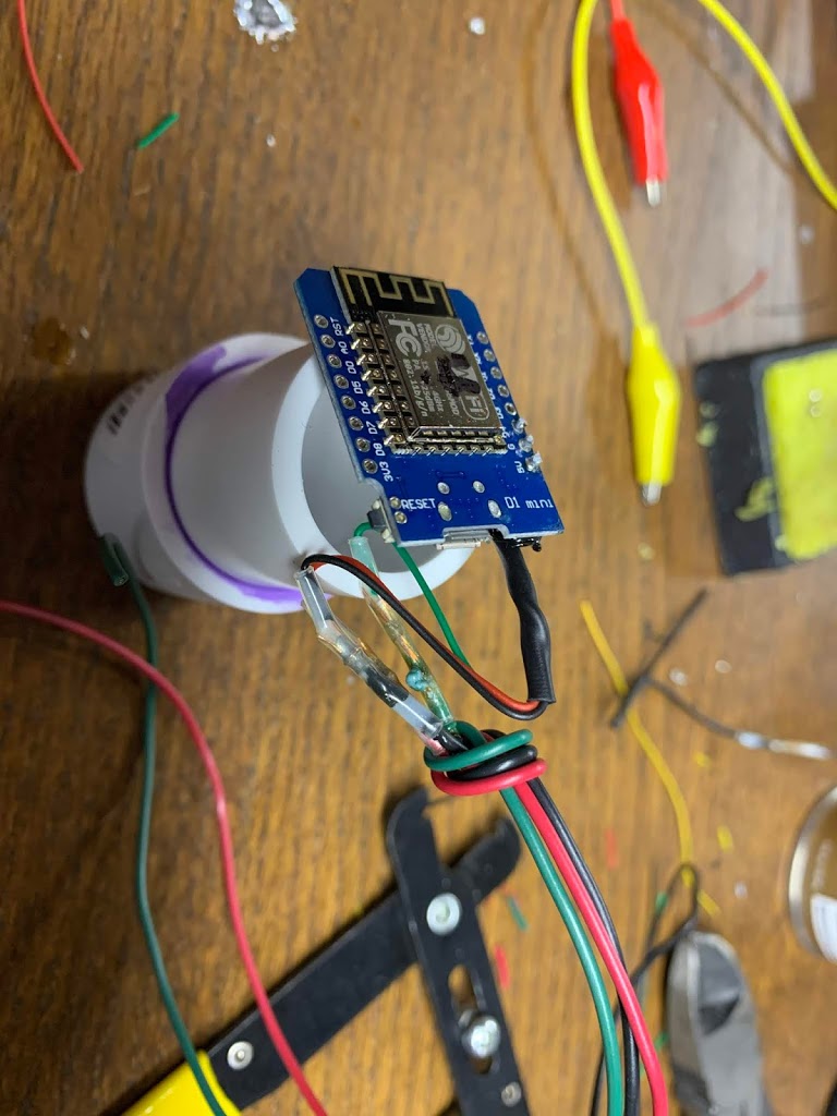
I’ve talked a lot about how the D1 (as well as ESPixelStick and PixelPop fit in 1″ PVC, making them easy to weatherproof. I decided to take that to heart and made some little controller modules out of 1″ PVC and end caps. I made a few 12v and 5v versions…
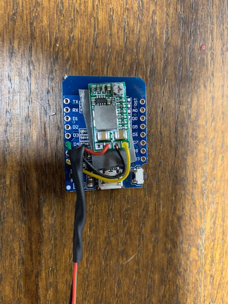
For 12v version, I attached a tiny buck convertr to the back of the D1 using auto trim adhesive tape. It provides a strong, non-conductive, cusion.
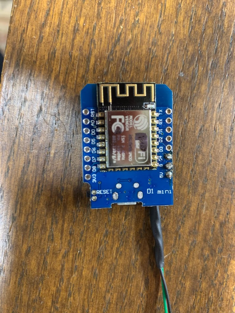
The back of the D1 is clear for some heat dissipation, and the WiFi antenna is unobstructed.
1″ PVC with one end cap glued on. The other has a hole big enough for the power and data wires.
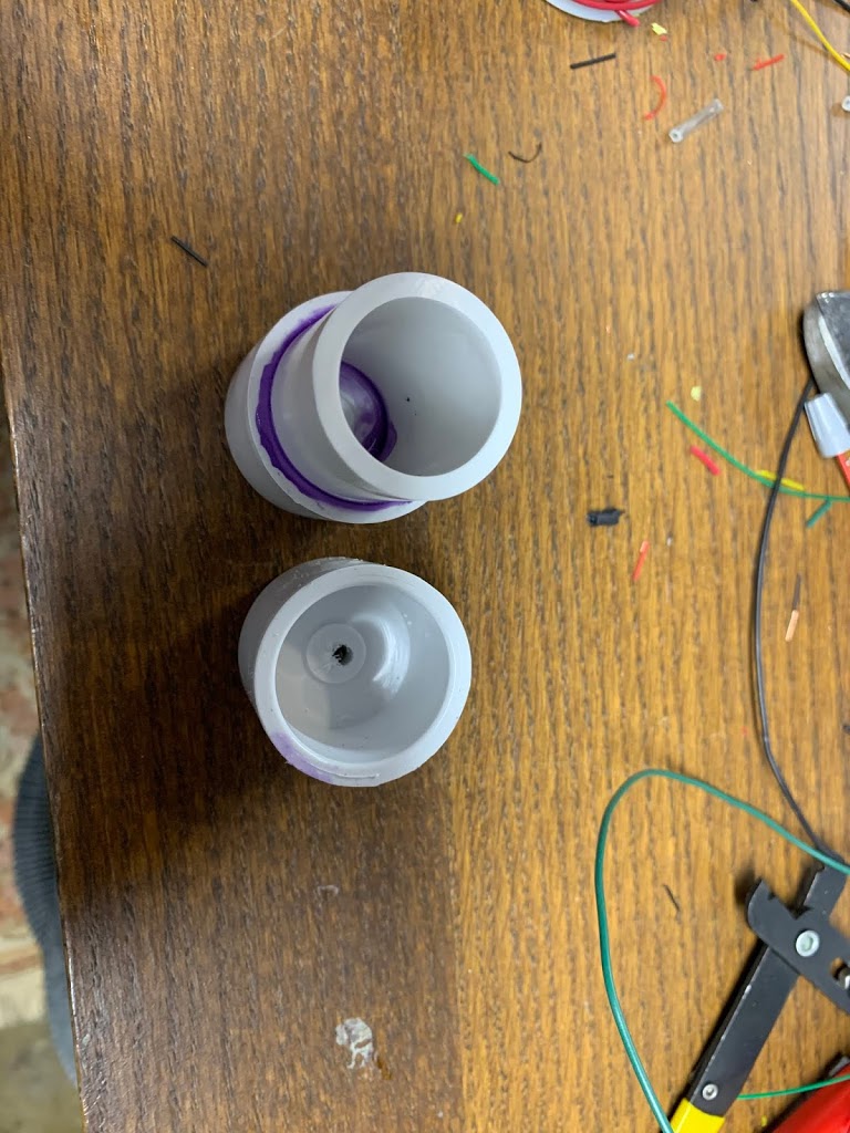
I minimized space by making the pipe just long enough for the end caps, since I don’t need anything bigger.

While probably overkill- I coated the circuit board connections and shrink-wrapped wires with RTV silicone. I also put some in the bottom and sides of the pipe so the circuit won’t “rattle around” inside. Hopefully this will prevent strain and flexing of the soldered wire connections, which I see as a failure point with-use.

The completed product. The wires are shrink-wrapped (with silicone inside) and silicone glued into the hole in the end cap. (There is a knot inside for additional strain relief.)
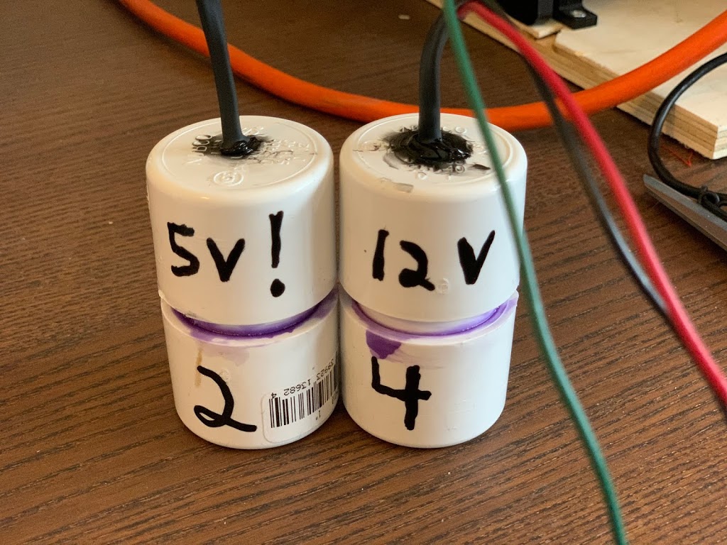
I wrote the voltage and controller number on the outsides so I can identify them easily. The controller number tells me what IP address and starting universe number is assigned to each controller. For example: #4 is ip: 192.168.1.104 and starting universe is 40 (universes 40-43).
The red and black wires just connect to the same power as the pixels, and the green wire connects to data. Depending on the pixels and how far away the controller is- a resistor may be necessary on the green line. This can be soldered and shrink-wrapped into the installation if-needed. As I noted before- I’ve found the need for a resistor and the actual value of it to be very variable, depending probably on the exact input voltage and the manufacturer of the LEDs. My rule of thumb is if they flicker and don’t render the display properly- I start with around 50 ohms and work my way up from there.
The only problem I have now, which I admit I should have though of, is there is a problem doing over-the-air firmware updates on these. I think it is a problem with the D1 Mini, and it probably works fine on the original PixelStick. If I upload firmware over the Web interface- the WiFi SSID, password, and configuration data is lost, and I don’t have any way of communicating with them anymore. Even with Fallback AP mode- I can’t access the Web interface anymore.
For now- if for some reason I feel compelled to update the firmware- I’ll have to cut open the little PVC capsule so I can access USB. I’ll then just have to make a new one.