New P5 Info Sign
Important Notice
This site is no-longer being maintained, and the content and links found here may be irrelevant and outdated. It is online for archival purposes only.
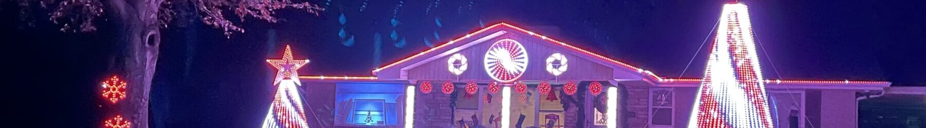
The old 8′ long P10 Info Sign in our carport was starting to show its age, especially since it is a “permanent” install, so it isn’t brought inside when the holiday season is over. Some of the panels have bad pixels, and the pvc frame and plastic were deteriorating. It was going to need to be refurbished for the upcoming season.
I got some P5* panels to try out, which have twice the resolution of P10s*, and… Wow! I love them. They are thinner and lighter than the P10s, and with all those extra pixels we can do a lot more with them. So, I decided to build a new Info Sign using P5s. To save a bit of money, I decided to only go six wide, instead of 8 like the old sign. Still- with all the extra pixels- it will be more versatile and just look a lot better.
As with our other more-recent panel-based matrixes, I decided to use 3D printed mounts and go “frameless”, wrapping the panels in plastic instead of building a full enclosure for them. These are “indoor” rated panels, so they need to be protected from the elements. They don’t need a heavy wood frame and plexiglass front though! Using them outdoors, even with protection, voids any warranty, so keep that in-mind if you do a similar project.
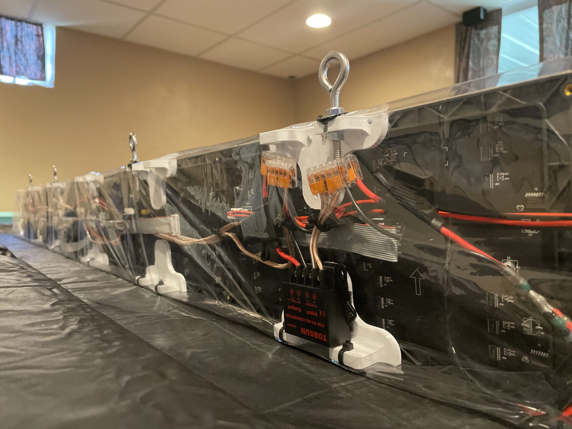
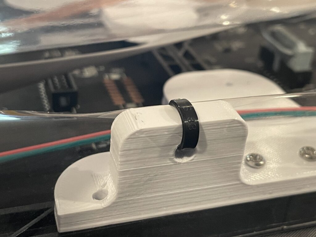
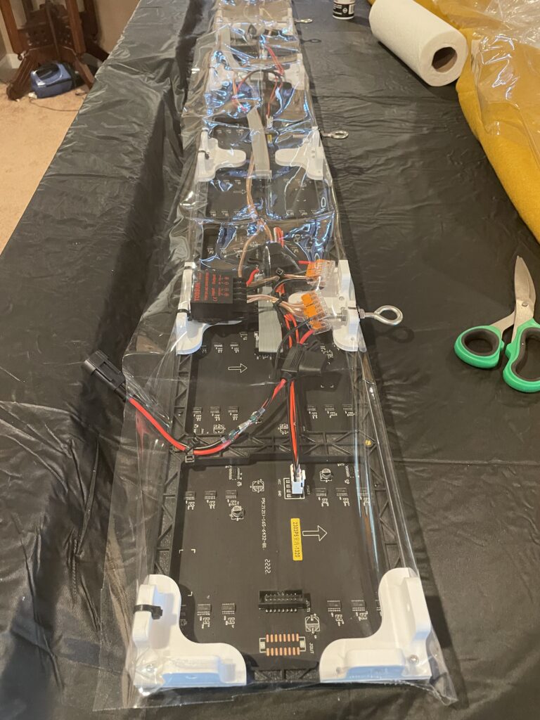
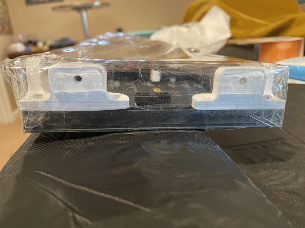
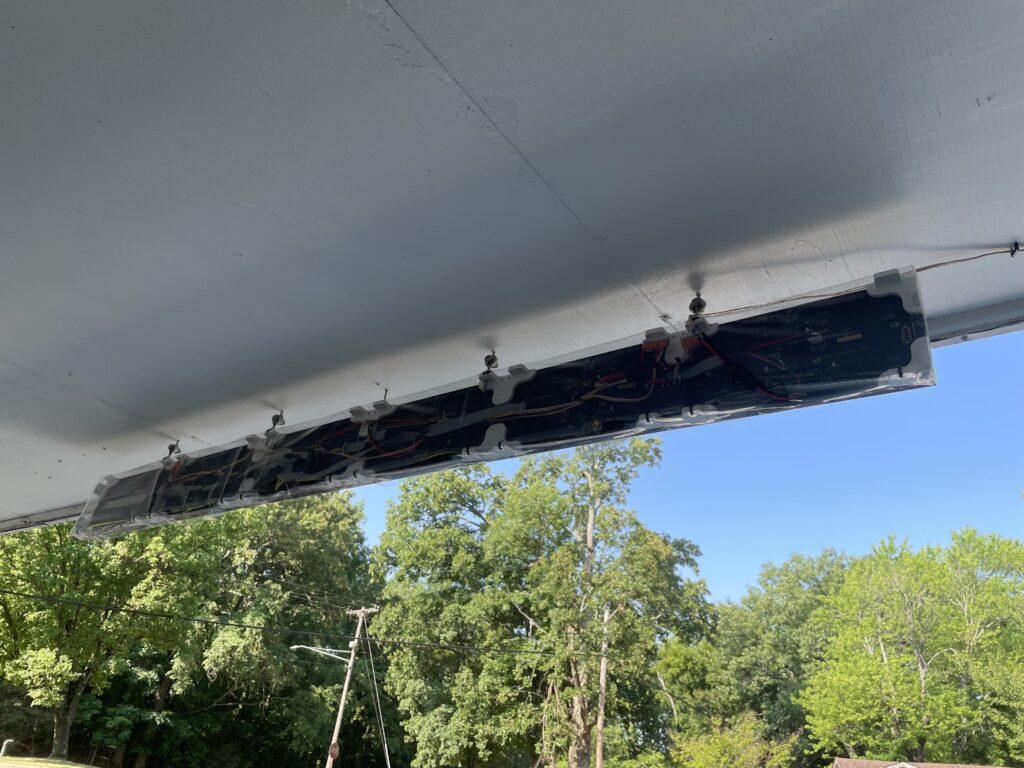
First, I 3D printed some simple brackets to connect the panels together. These are similar to the P10 brackets I’ve printed before, but they have tabs with screw holes, presumably to screw inside a frame. The P5s don’t really have any lip, so they can’t be slid into a dado-ed slot in a wood (or PVC board) frame like the P10s were. I’m not building a frame, but the tabs make nice spacers and additional securing points for the vinyl sheeting I’m using, and make it easy to hang the panel. The panels screwed together easily with 3mm stainless steel screws. If you don’t have a 3D printer- Wired Watts and other panel vendors sell joining hardware too.
After having power issues running panels off of 5v PSUs, I decided to use buck converters with a 12v PSU instead. This has worked well for our P10 columns- all three columns run off one 12v PSU, with each having its own buck converter. In this case, I’m using two 15A bucks- one drives four panels, and one drives 2 plus the controller. The Kulp Pocket Scroller, and all controllers that run off of Beagle Bone hardware, are VERY sensitive to voltage fluctuations, so I wanted to minimize the shared load. This lets me locate the PSU several feet away from the sign, with no adverse effects caused by voltage drops.
The 15A bucks are a bit of overkill- each panel only uses a maximum of about 2.5A (Full White, 100% brightness). It’s just what I had “in stock”. I run my panels at 50% brightness, which is more than sufficiently bright.
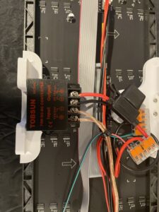
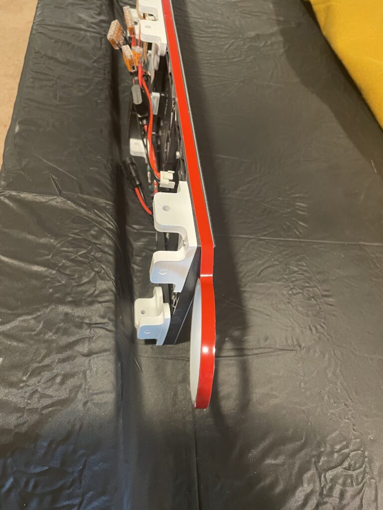
The buck converters are just hook-and-loop taped to the plastic mounts, close to the panels they are powering. I ran 12v to each one from a single input connector on the right side (from the back), which is where I want to feed power to. Both the 12v and 5v circuits are fused at both buck converters. 5A each for the 5v circuits, and 7.5A for the 12v. The PSU box is also fused.
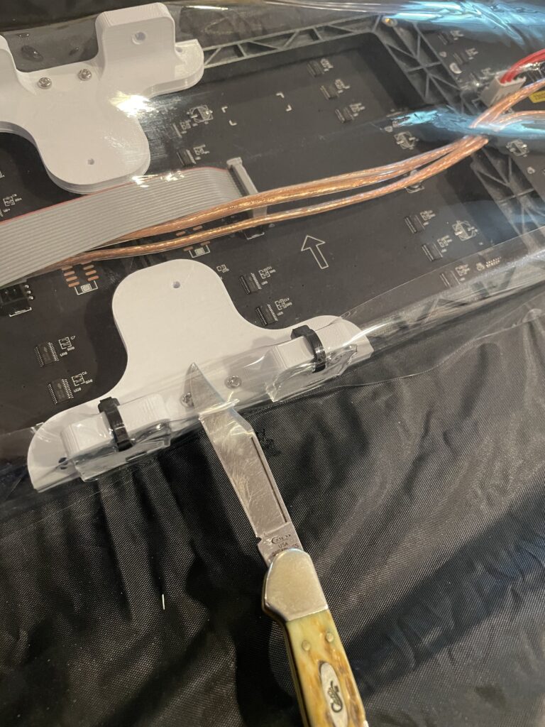
I’m re-using a Kulp Pocket Scroller as the matrix controller. I believe I could have run the whole thing off of one channel on the controller, but it’s always recommended to use multiple channels with fewer panels for reliability. I decided running each panel on its own channel would have really been overkill, so I decided to run two each. The panels come with daisy-chain HUB75 cables, which are just 16 pin ribbon cables.
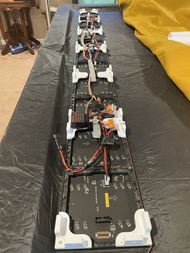
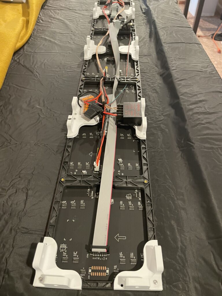
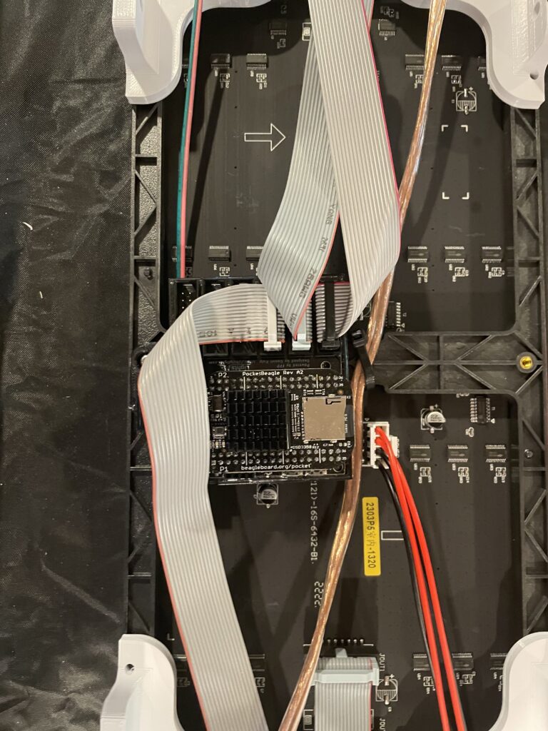
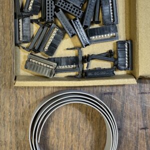
I had to make a couple of custom-length cables to reach the end panels from the centrally-mounted controller. You can order various lengths of cable online from Wired Watts and other panel vendors, or from Amazon. It’s easy to make your own though- just get 16-conductor ribbon cable and IDC ribbon connectors from Amazon or China. I just use a bench vise to crimp them- no special tool required. Just watch your polarity!
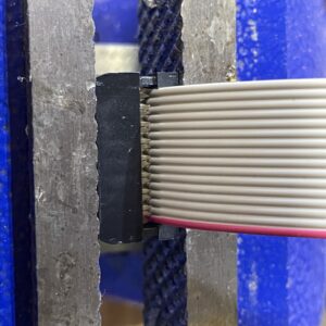
The controller is attached to another 3D printed mount that just has a couple of screw holes. Both didn’t line up with anything, so I just used one screw to connect it to one of the central panels. It’s tight and not going anywhere. I could also have just used hook-and-loop tape to mount it to one of the brackets. I zip-tied all of the wires and cables to the frames of the P5s just to keep them from moving around too much. The frames have about 1mm of clearance to the circuit board. Similar to most of these projects- it ain’t pretty, but it works.
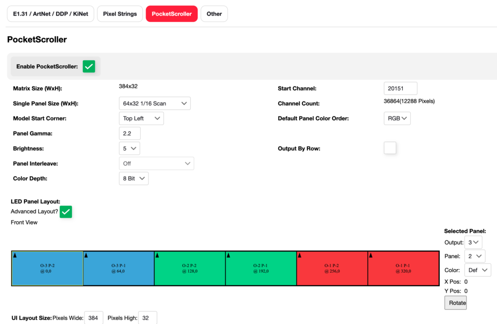
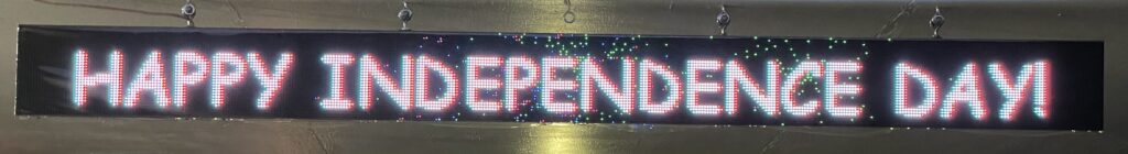
After assembly and wiring it up, I tested it using FPP’s test patterns and an Independence Day sequence I threw together. Here is the configuration in FPP:
After testing, it was time to wrap it up for weather protection. For our previous panel-based signs, I used self-adhesive “sign” vinyl, which comes in rolls that are 12″ wide. I didn’t have enough available for this sign, so decided to go a slightly different direction. I found a vinyl table cover on Amazon that was cheap. In hind-sight I also could have just gone to Walmart or a home center and picked up a clear shower curtain. The table cover is supposedly UV stable though, but I will see how well it holds up in the sun. If it fails- I’m ordering another roll of the sign vinyl anyway.
The advantage to the table cover/shower curtain vinyl is one piece can be used to wrap the whole sign. With the 12″ sign vinyl, it takes two sheets- one in front and one in back- to wrap the panels, which means there is a seam for water to potentially leak in. Of course the other problem is you can only make a sign one panel high, without having seams in the middle of your display. You can build a very-large P5 or P10 sign using sheet vinyl.
Here is a slide show of wrapping the panels in vinyl:

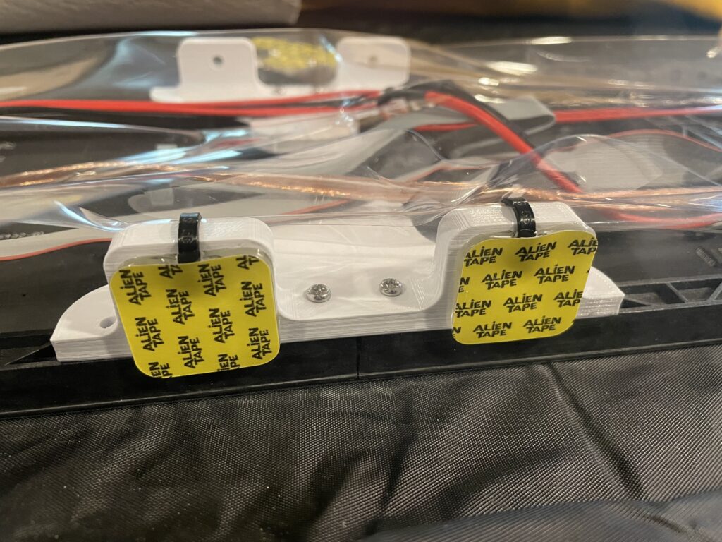
Double-sided automotive “trim” tape. This was the perfect size to use along the edge of the panels to hold the clear vinyl. 
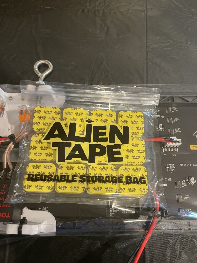
The vinyl that wraps around the front is secured to the bottom with more double-sided tape. I used zip ties for a bit of extra security for the front vinyl. These Alien Tape pre-cut squares turned out to be the perfect size to fasten the back half of the vinyl to the bottom brackets. Alien Tape squares, ready to hold the back vinyl in-place. Attached eye bolts with sealant to four of the top brackets for hanging. Eye bolts installed. Cut some notches through the vinyl inside the bottom brackets for drainage. The ends were folded over gift-wrap style and fastened with Gorilla Tape. Assembly complete and ready to hang. Back view. Assembly complete and ready to hang. Front view.
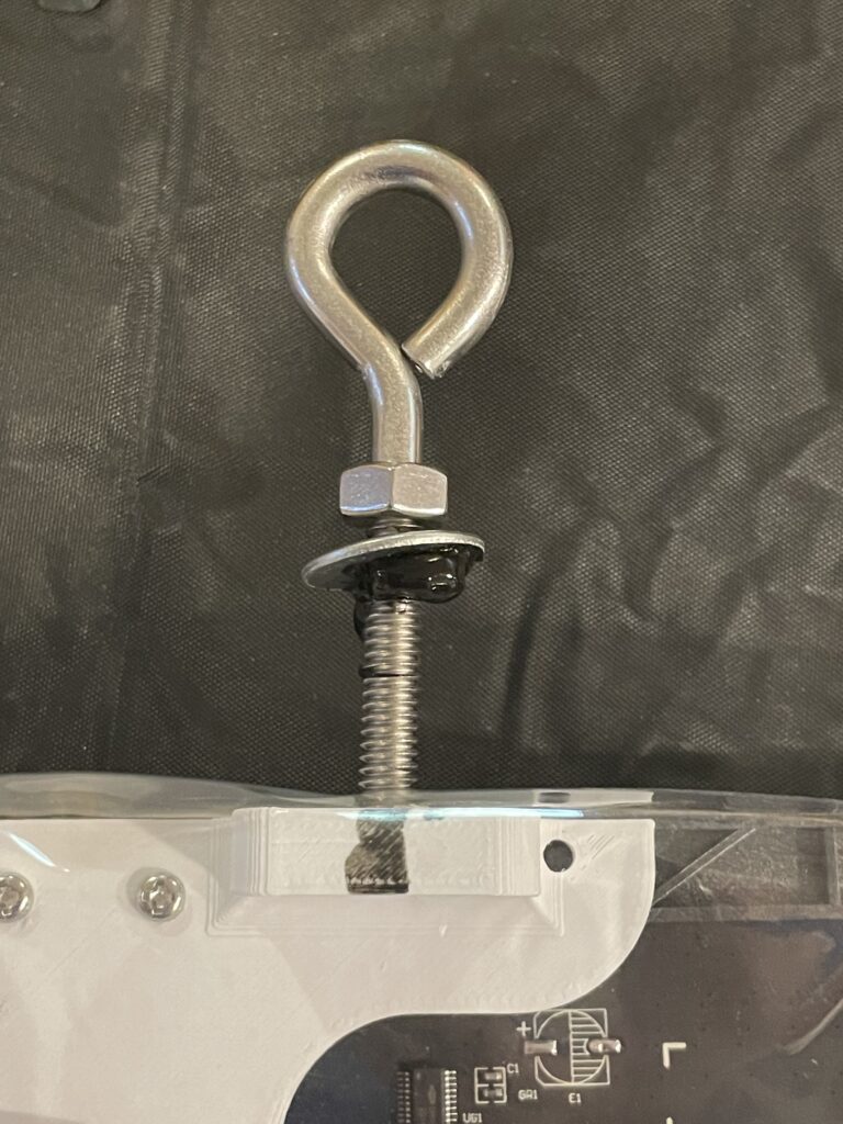

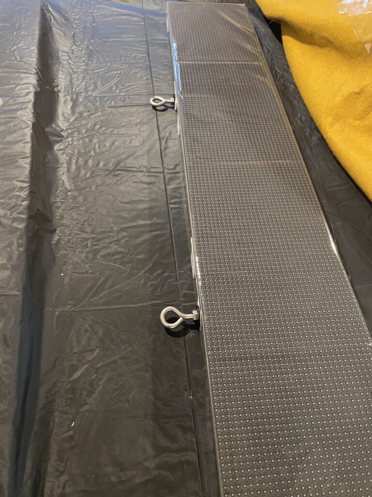
One sheet of vinyl wraps the entire sign, making it rain and weather proof. there are notches cut in the bottom vinyl just in case some water finds its way in. I also leave the bottom fairly loose so air can get in and keep condensation to a minimum and provide a bit of ventilation for the panels and controller. The eye bolts are securely tightened with silicone sealant so no water should be able to get into the top. The sign is actually mounted a little over a foot back from the edge of the carport soffit, so is fairly well protected from rain and snow anyway.
I used screw eyes to mount the sign to the ceiling, with the screw eyes being the same size as the eye bolts installed in the sign. I fastened them together with 1/4″ galvanized bolts and washers. This makes it fairly easy to take the sign down if I need to for maintenance/repairs, or if I just want to remove it between holidays/seasons. The intent is to leave it up “permanently” the same as its predecessor. I considered using hooks and just hooking the sign up, which would have made it easier to hang and take down, but I didn’t want it flapping in the wind. By accident I ended up screwing the bolts in at a bit of an angle, so the sign angles down slightly.
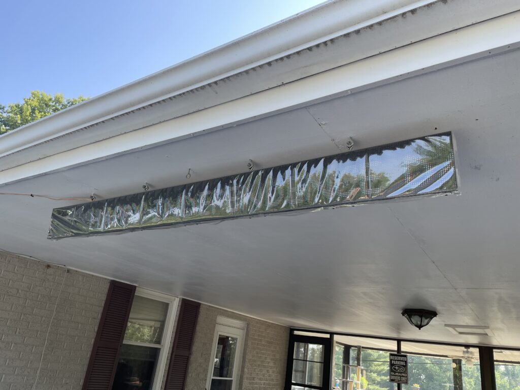
The front is a bit wrinkly since I didn’t used self-adhesive vinyl so it doesn’t stick to the front of the panels. I tried to pull it tight during assembly, but there is always a bit of slack. The vinyl should soften up and smooth out in the sunlight. Otherwise I may see if I can get it to shrink a bit with a hot-air gun. Of course, at night it doesn’t matter, and during the day the reflection isn’t as bad directly in front of it.
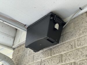
I mounted the 12v PSU in an ammo box in a corner behind a downspout so it hopefully isn’t too noticeable. It is just a PSU, with no controller hardware. I used the same vented box that housed the controller and 5v PSU for the original Info Sign. The power cord is run so it drops right next to an outlet, and can be plugged in and unplugged easily.
The end result is a much higher resolution sign that I think looks better than the old one. It weighs significantly less too, and the way I have it wrapped and mounted- it will easier to service if there is a problem. One thing I really love is since the controller is “built in” to the wrapped sign- I can tell at a glance if it is on and active. The previous sign used a controller in an ammo box, so the only way to tell if it was running properly for debugging a display issue was to get up on a ladder and open the box. I can see the Pocket Beagle’s activity LEDs easily from my office window. I didn’t bother installing an OLED display on the Pocket Scroller, but could.
(There is a channel issue that is causing a blue and red shift horizontally that I am still working out between xLights and FPP.)
The functional panels from the old sign will be re-used in other projects. I will likely build a couple of expanded Tune To signs to put in the yard. I might see if I can come up with some other props to use them as-well. 😊
Update (July, 2023): I never did figure out what caused the blue and red shifting issue. It had to be a channel problem between xLights and FPP. I had already verified that the channel numbers in xLights matched those in FPP, but still had the problem. I upgraded to the latest beta v.7 of FPP, and re-rendered the display sequence, and the problem disappeared.
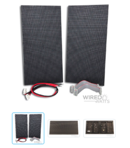
* Note: The LED panels we generally use in holiday lighting come in two forms, which reflect their resolution. Both are the same size, slightly larger than 1ft. W x 6in H x 1/2in. D (thick). The “P” refers to Pitch, which is the center-to-center distance between pixels. A P10 panel has 16 x 32 LED pixels (512 total) on 10mm (1 centimeter) centers. A P5 panel has 32 x 64 (2048 total) LED pixels on 5mm centers. It is possible to buy higher resolution panels, such as P1 and P2, but they are very expensive and more-often used in professional HD video displays, like video walls. They take more specialized hardware to drive them as-well. For larger matrixes, I’ve found using virtual video matrixes driven by a projector to be a lot more versatile and cost-effective. Some use HDTVs instead, but they are problematic in sub-zero winter temps.