
Sprite Extruder & All-Metal Hotend Install
Important Notice
This site is no-longer being maintained, and the content and links found here may be irrelevant and outdated. It is online for archival purposes only.
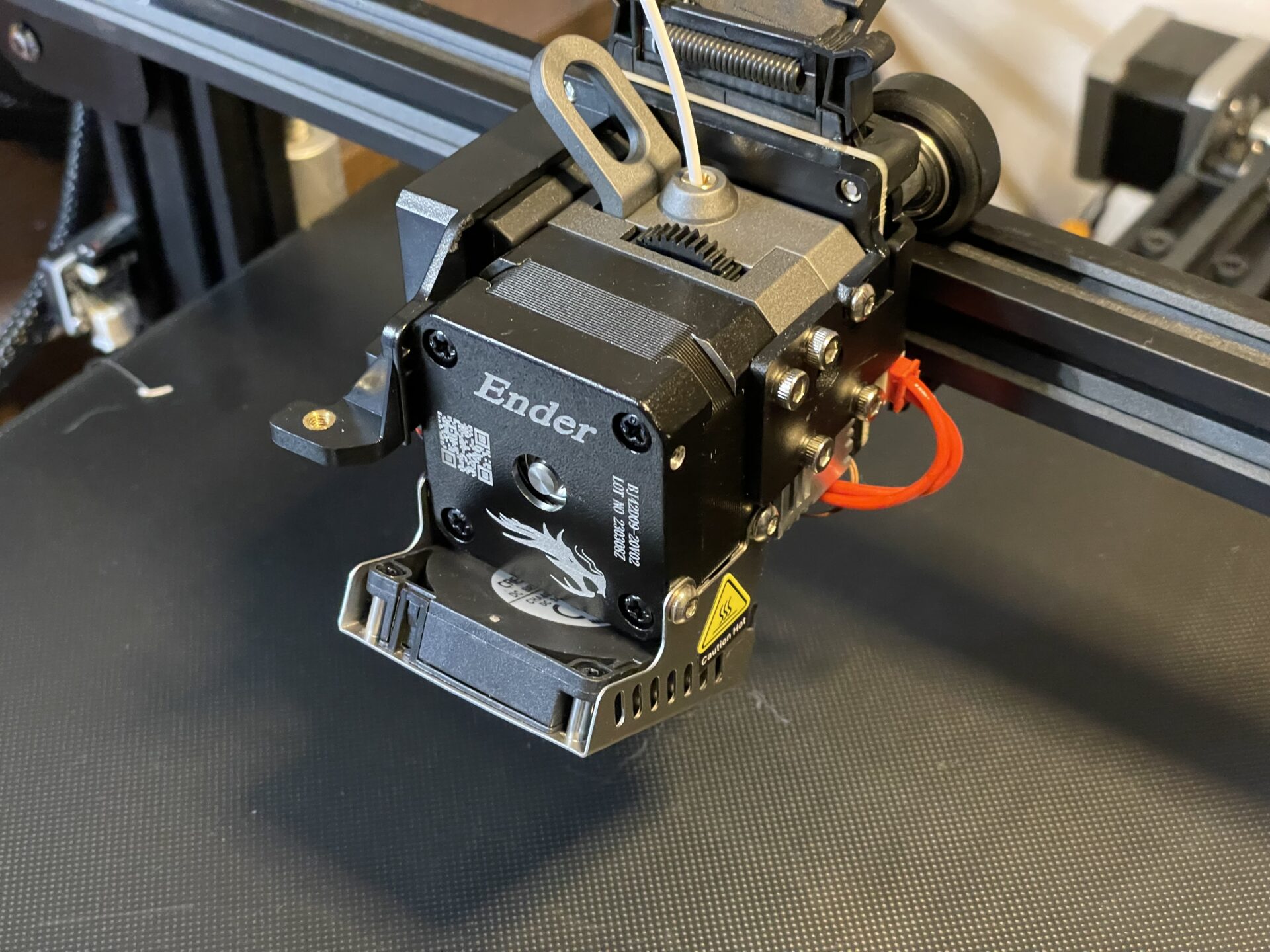
Creality has a Sprite Pro extruder and hotend designed to print at up to 300℃. It replaces the stock Bowden extruder on my Ender 3 Max printer, with a dual-gear direct-drive extruder assembly that feeds directly into the hotend. I was interested in it both for the possibility of printing TPU (flexible prints, similar to silicone or rubber) and hopefully getting better quality out of PLA/PLA+ and PETG filaments. Bowden tubes can be a bit “sloppy” and require longer/slower retraction distances. The dual gear system is a bit more precise, and the all-metal hotend should be a bit more reliable long-term than the original PTFE Bowden assembly.
I’m not going to cover the full install, as there are a lot of videos online for it. Here is Creality’s:
Looks easy, right? There are a few things omitted.
First, if your printer has a filament runout sensor, you will either need to abandon it, or get/print a new mount for it, and will need to extend the cable. It might be best to print the mount before you take the printer apart. Here is what I used:
https://cults3d.com/en/3d-model/tool/direct-drive-filament-runout-sensor-mount
I like it because it swivels enough to avoid any tight bends in the filament.
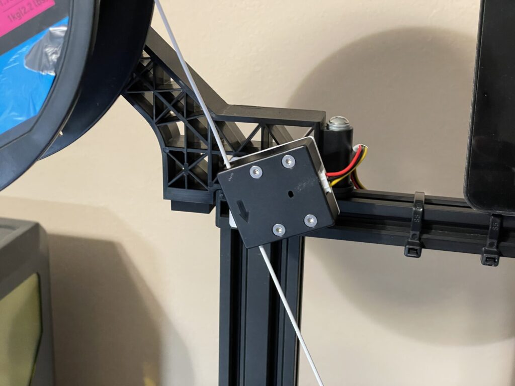
With a couple of longer M3 screws and T-Nuts, you can also just screw the sensor directly into the top rail, or even high-up on the side rail if you don’t ever print tall pieces. The stock 3-wire cable that goes to the sensor wasn’t long enough, so I spliced in some “LED” wire to extend it. I actually used ClickIts from our light show repair stock for the splices, and they have worked great so far.
You may also need a new top-mount spool holder, or a filament guide with bearings. Consider printing them first too. I actually just rigged the factory holder to the top using an M5 screw and T-Nut, and a couple of plastic washers. The plastic washers were necessary as I had to cut a notch out of them so they would fit properly. You can see it mounted behind the runout sensor in the picture above.
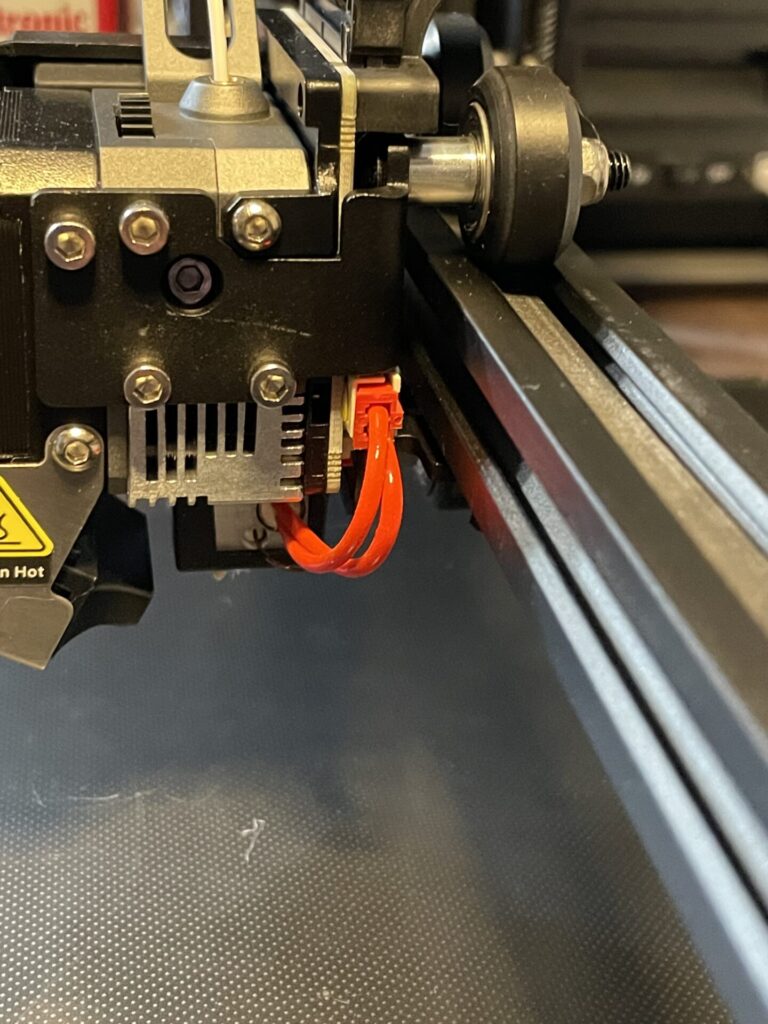
The Sprite Extruder as-shipped does NOT have the heater “tube” wires connected. You will see a couple of red wires going between the nozzle heater and the part cooling fan nozzle. They may have a sticker on them that says:Please insert it into the adapter plate before using.Unfortunately, “it” isn’t really defined, and the adapter plate would normally be the “Pro” X-axis trolly that you connect the extruder to the gantry with. So- it’s confusing.
The connector for the heater is tucked behind the fan. Pull it out, and plug it into the larger white connector on the circuit board above and behind it. This drove me crazy, as I thought my brand-new extruder was DoA. This information is not in the printed instructions or in the install videos I’ve found.
When it comes to connecting everything to the printer’s mainboard, there are a few surprises here…
- The board enclosure may have a cooling fan. If it does- it connects to the same terminals as the always-on heat break cooling fan. I just stripped a bit more insulation off the conductors and wrapped them around the pins for the new Sprite cooling fan.
- All of the connectors on my board are coated pretty heavily with hot-melt glue to prevent them from disconnecting in transit. You have to pry it off of the stepper, thermistor, and “KFan” (parts cooling fan) connectors just to unplug the old ones. The very-careful use of a rework heat gun, or even a hair dryer, can help soften it. Gently pry it off, using care not to break anything.(!)
- You will need to remove some tape and zip ties to undo all of the cables going into the controller box.
- The ribbon cable wires to the plugs and pins that need to be connected to the board are not separated far enough for them all to reach their connectors. VERY GENTLY pull apart about 2cm more of the conductors in the ribbon cable so they can reach all the board connections. Some of the wires for the JST connectors come from different parts of the ribbon cable as-well. This seems wrong, but it’s the way it was designed.
- Once everything is connected, the ribbon cable will tend to completely block the cooling fan. Gently fold/roll the cable over itself to make a smaller profile, and use electrical tape or a zip tie to keep it that way. The cooling fan will then be able to actually blow on the board again.
- Some videos say to just leave the unused ribbon cables from the old extruder in-place because they are tied to the Z stepper and X-stop switch. I just don’t like leaving unused cables and connectors in an assembly. I just gently pulled the unused wires/connectors out of the wire loom. I had to split a ribbon cable to get them all pulled out
I don’t use a “CR-Touch” bed leveling sensor, but went ahead and connected that part of the cable to the board anyway so I don’t have to mess with it if I eventually do get one. The Sprite has a connector for it, and even comes with a little cable to hook it up. I just saved it for later.
There are a couple of redundant JST connectors on the control board end of the ribbon cable with no label on them. I loosely tied them together just so they aren’t rattling around in the box. They are unused.
After getting everything connected. I organized all of the cables as flat as possible and taped/zip tied them together into a neat bundle so they are protected and sit nicely into the original cable slot. on the bottom of the printer. I then re-assembled the controller box.
Changes that need to be made after the install:
Per the instructions, you need to change the E-steps to 424.9. This is the number of steps necessary by the extruder’s stepper motor to eject 1mm of filament. I found after running a calibration on it that this is the perfect amount and shouldn’t need to be changed once set. You can set it using the printer’s control panel.
Here is what to do (covered in the instructions that come with the Sprite Pro as-well):
- Navigate to Control -> Motion -> Steps/mm, and adjust the Esteps/mm value to 424.9. Then navigate back to the Control menu, select Store Settings, and hit Enter.
- On some printers, such as the Ender 3 V2, the printer will not allow you to set the e-steps value this high. For those printers, follow these steps:
- On your computer, create a new text file with the contents:
M92 E424.9
M500
Save this file as “esteps.gcode” and save it to a microSD card to put in your printer. - Insert the microSD card into your printer. Use the menu to select the esteps.gcode file and press Print.
- When this file completes printing, which should be instant, the e-steps value will be set and saved to the printer’s memory. You can remove the esteps.gcode file from the microSD card.
- On your computer, create a new text file with the contents:
You will also need to adjust retraction to .8mm and retraction speed to at least 35mm/s in your slicer* (like Cura). Unfortunately this means your old G-Code files won’t print very well, as the large retraction necessary for Bowden tube setups is way too much for a direct-drive extruder. These are all covered in the instructions.
Another big thing- you will need to re-tune the PID settings for the nozzle heater. The settings that work for the default head will not work well for the new Sprite, and you will see very wide temperature swings otherwise. It will also take a very long time for the temperature to stabilize enough for the printer to signal it is ready to print. Great instructions for setting Auto PID are here:
https://www.3dmakerengineering.com/blogs/3d-printing/pid-tuning-marlin-firmware
Remember to save the recommended PID settings, per the instructions, and also by issuing an M500 command via a terminal.
Here are the general steps to Auto-Tune the PID of the hotend, to stabilize temperature management:
M106 S255     ;Turn on parts cooling fan. (recommended)
M303 E0 S210 C15     ;PID Auto Tune. Extruder (E0), 210℃, 15 passes.

(It will take several minutes to complete)

M301 P15.33 I1.31 D44.86     ;Save Auto Tune values.
;(Change P, I, D values in the command above to whatever Marlin recommends.)
M500     ;Save to NVRAM (SD Card)
Of course you will have to re-level/tram the bed. I cranked it down quite a bit before homing the head for the first time, just to avoid burying the head in the build plate. I didn’t measure the distance to the bed for both heads, so I don’t know if the Sprite is closer or farther away than the stock head. I “level” the bed the old-fashioned way with a slip of paper, but of course you can use whatever method works for you. If you do use a CR-Touch or similar auto-leveling sensor, you will need to re-calibrate it with the new head.
While I was at it, I adjusted the X and Y belt tensions, lubed up the Z lead screw (using a “dry” silicone lubricant), and adjusted all of the roller assemblies so all of the rollers make solid contact with the rails and everything moves smoothly.
The Sprite extruder shifts the “Home” X position a few mm to the right from stock. You can’t really change this because it is based on the X-Stop switch. So, you lose a bit of overall print area. I never print anything that close to the edge of the bed any way.
I’m still experimenting with it, but you should be able to increase the feed rate/print speed. (At least for PLA.) Cura defaults to 50mm/s, but I’ve heard some folks have it cranked up to 100mm/s or more. Right now I’m trying 75mm/s, with mixed results. I need to lube and tighten everything up a bit more. Also…
* I’ve been having issues with stringing no matter what I print with (PLA/PLA+, PETG). I’ve been experimenting with the retraction and temperature settings. The all-metal hotend and very efficient heater seem to make it more of an issue. Right now my best advice is print at the lowest recommended temperature for your filament, and try different retraction settings. I’m using 1mm retraction with 45mm/s retraction speed with some success. I’m still getting tiny “hairs” on many move operations.
This may be helpful, although I’m still trying different options with it:
http://retractioncalibration.com
The board in my printer is v.4.2.2. I might upgrade to the newer board with silent stepper drivers eventually, but for now most of the noise the printer makes seems to be from the cooling fans. I did upgrade to the latest Creality-supplied firmware for it.
Update:
I tried installing the Sprite-specific firmware from Creality, found here:
https://www.creality.com/pages/download-sprite-extruder
It is supposed to allow up to 300℃ temperature setting as well as fix the home position for the head. It is made specifically for the Sprite with CR-Touch auto-leveling, so it flat-out doesn’t work with my setup. There isn’t even a way I can find to disable the CR-Touch and auto-leveling mode.
It is also set for Chinese, although you can reset the language to English easily:
- Click the control knob.
- Scroll all the way down and then up one item.
- Click the control knob.
- Select English.
- Click the control knob again.
It’s helpful to remember this for any firmware update/upgrade, since the default language is Chinese.
In the end, I reverted back to the upgraded “stock” Ender 3 Max firmware, which can be found here:
https://www.creality.com/pages/download-ender-3-max
Updating the firmware is easy on Creality’s newer 32-bit boards. They already have a boot loader and can load new firmware off of a micro-SD card. Some advice on this:
The printer’s “NVRAM” is actually a hidden file on the SD card that you need to leave in the printer. DO NOT format and use this card for new firmware, or you will wipe out the settings file! Use a new/spare SD card. Be sure you download the proper firmware file from Creality that matches your printer model AND board version. The board will likely be a “4.2.2” or “4.2.7”. Be sure you use the right one.
Just copy the appropriate firmware .bin file downloaded from Creality to a newly formatted (FAT/DOS) SD card, and swap it for the SD that you keep in the printer. Turn the printer on. It may take 30-seconds or so before you see the “Ender” dragon logo and then the control screen. Once done, you can remove the SD card and replace it with the regular one you leave in the printer. Then power the printer off and back on again. Don’t leave the firmware upgrade SD in the printer!
You can upgrade or downgrade at-will using this SD card firmware update protocol.
Another Update:
(August, 2023)
I wanted newer firmware so I could add manual bed leveling, which moves the head to each corner of the build plate as often as you need. This is a bit easier than manually moving the head and bed after unlocking the steppers, which isn’t recommended, or using the X/Y motion options in the control panel to move it manually. It is also much more consistent as it will always go to the same coordinates at each corner.
Side note: I don’t use paper anymore to tram/level my bed. I use a .006mm feeler gauge. This is a bit more consistent than paper.
I also wanted to add a higher temperature limit (300℃), even though I don’t currently print ABS, replace the default ABS preheat configuration with one for TPU, and change the PLA defaults. Finally I needed to change the distance (mm) settings for filament runout and filament change as they are set for the stock Bowden tube extruder arrangement by default.
So I downloaded the latest version of Marlin (2.1.2.1) and spent a few hours configuring, building, and testing it. I added my tweaked configuration for the Ender 3 Max (original version) to my Github here: https://github.com/neowolfwitch/Marlin
More information about Marlin can be found at: https://marlinfw.org
(Marlin is the OEM firmware for Creality FDM printers.)