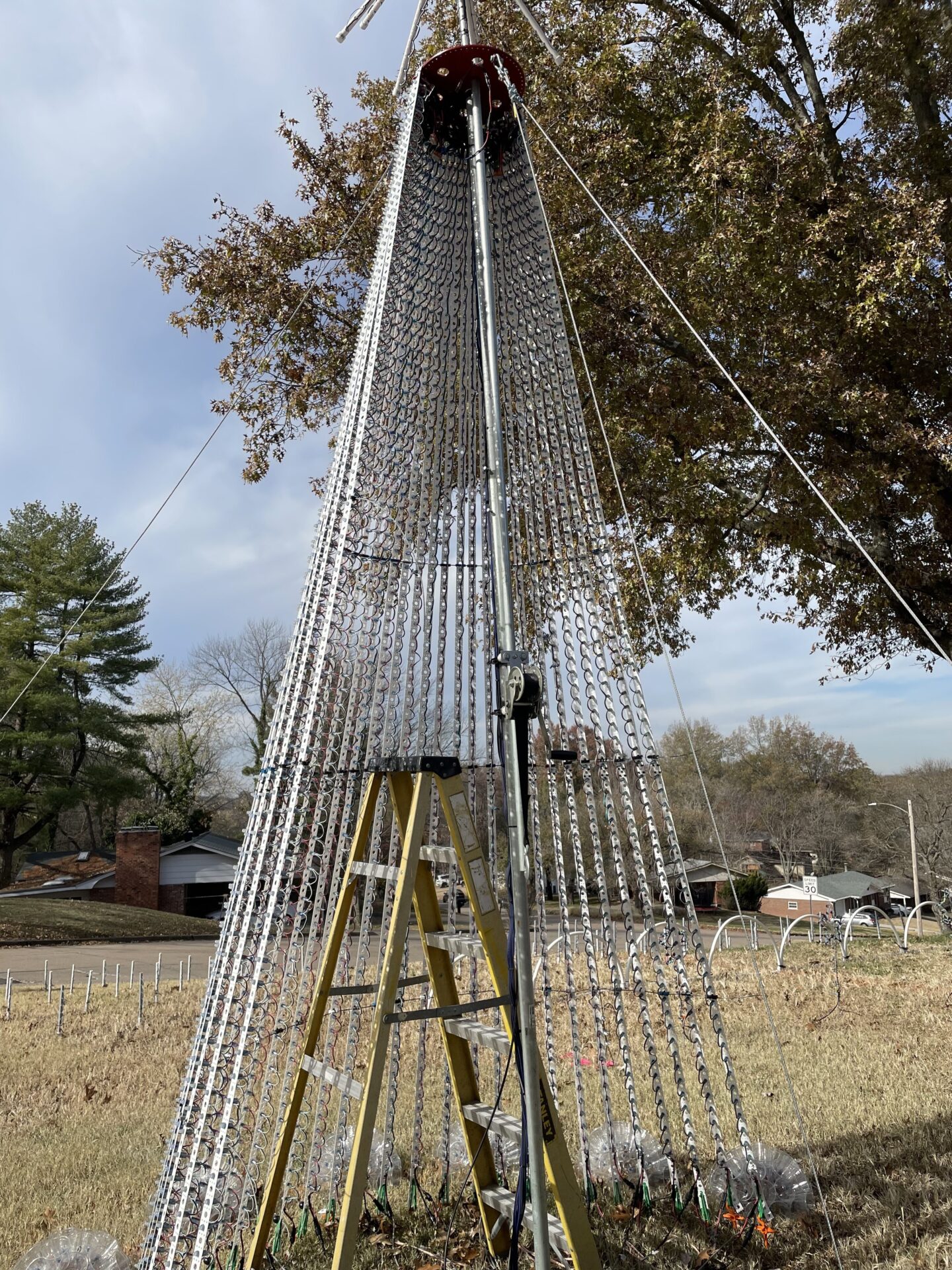
Mega Tree Wiring
Important Notice
This site is no-longer being maintained, and the content and links found here may be irrelevant and outdated. It is online for archival purposes only.
I’ve received some inquiries from social media about why I pulled the fuses out of my K16A-B controller for our megatree and how it is wired.
First, some background…
This year we had planned on going from 2″ spacing on the megatree strips to 1″ spacing. Going from 75 pixels per strip to 150. We also added 8 more strips for a 32 strand tree. I re-designed the K16A-B controller box for this. This requires four PSUs (Power Supplies) to run the whole tree, instead of the original two. Later in the season we abandoned 1″ spacing for this year, but I went ahead and re-did the K16A-B box anyway to accommodate 1″ spacing in the future.
So, some math:
The maximum current a pixel uses is .06A, but since we never run at 100% brightness, we can reduce this. We actually run most of our show at only 20% brightness. Still, I build quite a bit of overhead in for safety, so I use .04A for our calculations. Our original plan uses 150px per strand x 32 strands, which equals 4800px. 4800 * .04 = 192A. This requires 4x our commonly-used/available 5v 60A PSUs. Another rule of thumb is to only run a PSU at 80% of its maximum current, so 48A per PSU. This actually works out perfectly. (48 * 4 = 192)
The K16A-B only supports two PSUs, and on top of that only supports 5A fuses for each of its 16 outputs. We are running two strands per port (for a total of 32 strands). 300 pixels per port * .04 = 12A, so- we risk blowing the port fuses if we use them anyway. (At 20% brightness we would actually only peak at .012A/px, or 3.6A per port in this case, but again- we are adding overhead for safety.)
And then, there’s more:
Another consideration is pixel data is based on negative/ground, so all pixels being driven from the same data channel need to have their negative (-) ports tied together if being run from separate PSUs. Just to avoid any potential issues, I tie all of the negative (-) ports together for all PSUs in the same controller box.
It is fairly common to refer to the negative (-) DC pole as “ground”. This isn’t technically true, as it may not actually be a real “ground”, which by definition is connected to the Earth. This should NOT be confused with mains (AC) ground. DO NOT connect the mains (AC) ground to the negative (-) pole of any PSU. I’ve seen people do this- it’s dangerous! You can burn out the PSU depending on its design, and you may create an electrocution hazard. You may also end up introducing excessive AC noise into the data circuit.
What CAN’T happen is to have the positive (+) terminals from different power supplies connected together. This can cause the voltage regulators in the PSUs to fail, in some cases spectacularly, by “letting the magic smoke out”! Some PSUs can handle this, but the Mean Well and similar industrial supplies many of us use can’t. So- we can’t just connect two power supplies together for each side of the K16A-B, and we don’t want to risk such connections “in the field” when assembling the tree.
So, long story short, we can’t just power the whole tree directly from the K16A-B ports.
We also have to consider the power injection needs of the pixels. They have extremely thin wiring, and because of that and the voltage drop over a distance of wire, we need to add power after a certain amount of pixels. For 5v systems like ours, the rule of thumb is to have no more than 50 pixels between injection points, or roughly one injection point every 100 pixels. (For 12v systems the rule of thumb is every 200 pixels.) We can stretch this (for our originally-planned 150 pixel strands) to 150 pixels because of the lower brightness we use. So in any case we need to power inject at the top and bottom of each strand of our tree. We need to insure that both ends of each strand are powered by the same PSU. If we were to try to provide power from the K16A-B, we would end up with positive ports overlapping for at least half of the strands.
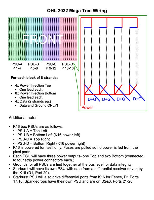
So here is my documentation for how the tree is wired:

(You can disregard the notes about the Starburst (topper) and other yard elements, which use the differential ports on the K16A-B and have their own PSUs.)
I do have a confession: In 2022 I screwed up and wired the actual tree backwards, starting from the left side (front). It just mirrors my diagram and I had to alter the model and re-render everything in xLights. It made for a cable mess too because I had set the controller box up with the diagram above in-mind.
So- two strands receive data from each port of the K16A-B, and every 8 strands are driven by a separate PSU. Because I pulled the port fuses from the controller, only ground (-) and data are sent through each port, so there is no mixing of the positive ports from the controller’s power supplies, and I don’t have to alter the typical 3-conductor data runs. An alternative to pulling the fuses would be to use two-conductor cables and just not connect anything to the positive (+) terminal of the Phoenix connectors (ports) on the controller. Because I already had 3-terminal connections built for the controller from past years, pulling the fuses was more logical. If I later decide to use the controller somewhere else and I do need to power the pixels through the port connectors- all I need to do is replace the fuse(s).
There are four 14Ga cables that run to the top of the tree for power injection for the tree itself. I’m using WAGO busses to split the power runs up for the strands. These are easy and fairly cheap to build and work great! An alternative would be actual bus bars and a LOT of extra wire, or something like big waterproof wire nuts (expensive!).
By doing things this way, I’m already set if/when we change to 1″ strip spacing, or if we build a taller tree with even more strands or pixels. We can easily incorporate more PSUs if necessary, without worrying about which PSU is tied to which the controller connection.
I hope all of this makes sense. 😊 Final safety note: FUSE EVERYTHING. 5v (in our case) may not sound like much, but it can overheat and burn a wire or circuit just as well as higher voltages. Overheating wires or circuits can cause fires. I pulled the fuses from the controller because we don’t want current flowing through those connections, but I have all of the power injection circuits fused.
I could have run the whole tree only using 4 ports of the K16. Running only two strands on each port helps isolate failures though. If something goes wrong on a port, like a bad pixel, at most it can only take out two strands, instead of 8. If I were running 150 pixels per strand- it would also reduce the frame rate and would really be pushing the K16 near its limits, which I don’t want to do.
