
Enclosure Temperature Control
Important Notice
This site is no-longer being maintained, and the content and links found here may be irrelevant and outdated. It is online for archival purposes only.
During our 2022 lighting season, from Thanksgiving to New Years, the outside temperature ranged from -6℉ to 70℉.
When I built a new projector enclosure, I had to build it with four (!) cooling fans/vents, three on the sides and one on the top, so I could keep the temperature inside the enclosure under 100℉ at ~70℉ outside the box. At the time- I was only concerned with the projector overheating, and hadn’t considered what would happen if it got too cold. The projector’s operating temperature range is 40-100℉. Below the lower limit- I was concerned about the danger of thermal shock shattering the lamp and/or the optics when the projector was powered up. This became especially true when the temps dipped down to, and below, 0℉.
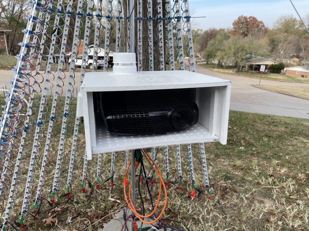
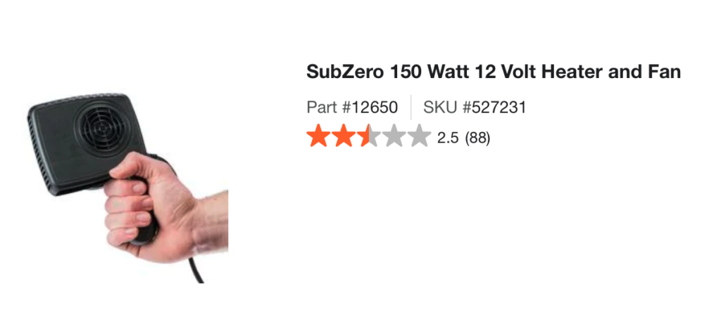
I ended up adding a portable automotive defroster into the enclosure as a heater. More information is at the bottom of this article. This is sort of a flat hair dryer like device that plugs into a 12v car outlet. It was just the right size to fit in above the projector. I rigged it up to a 12v PSU and set that up to be controlled via FPP. I also added switches to the fans so I could manually turn them on and off as-needed. Finally- I added a remote-read thermometer to the enclosure so I could monitor its temperature from inside the house.
This manual temperature control system worked well, but I had to be sure to keep an eye on the temperatures inside and outside of the enclosure, and manually toggle the fans or heater on as-needed. As y’all know by now- I like to automate everything! So, for 2023 we will be running two projectors with automatic heating and cooling for their enclosures.
Some more details of how the projector enclosures are built can be found here and here. I’m re-designing the original, and then duplicating it for the 2nd one later this year, and will post some kind of a build update when that’s done. For now- I wanted to cover the control system I built for them. This can be use for projector enclosures, controller boxes, or anything else that needs to be kept at a reasonable temperature while operating outside. Of course you can adapt it to your own needs. 😊
First, hardware-wise I am using new higher-capacity 12v fans. These push more air than the wimpy ones I installed last year. In fact, one of them pushes close to the same amount of air as the projector’s cooling fans, so it rarely needs more than one fan running. I’m establishing a single heating stage, and two cooling stages. Cooling stage 1 “Fan 1” will be the side vent fan closest to the heat output on the projector. (Closest fan on the left side while looking at the front.) “Fan 2” will be the other left side fan, along with the right side fan. These should rarely run, but are added security. I’m using similar portable defrost heaters as before for heating. My hope is that by thermostatically controlling these three stages, we can keep the projector as close as possible to its operating temperature range.
We use a Raspberry Pi running FPP for each projector. This provides projector control via a USB to Serial cable, and a virtual matrix/video feed via HDMI. I want to use the same Raspberry Pi to control the heater and fans. So…
First, we need a way to measure the temperature. The Raspberry Pi has a CPU thermal sensor, but obviously that doesn’t give us a very good picture of the external temperature. Any on-board sensor will not be very accurate because many of the components on the board produce their own heat. I looked at various analog and digital temperature sensor options, and decided the best thing to use would be a DS18B20 “1-Wire” digital temperature sensor. These are cheap, readily available, and very well-documented. It is very easy to use them with a Raspberry Pi.
They are packaged like transistors. You can also buy them as complete “temperature probes”, but that just adds unnecessarily to the cost. I found the following article helpful for wiring the DS18B20 to the Raspberry Pi and configuring it. Just skip over the LCD display portion of it.
https://www.circuitbasics.com/raspberry-pi-ds18b20-temperature-sensor-tutorial/
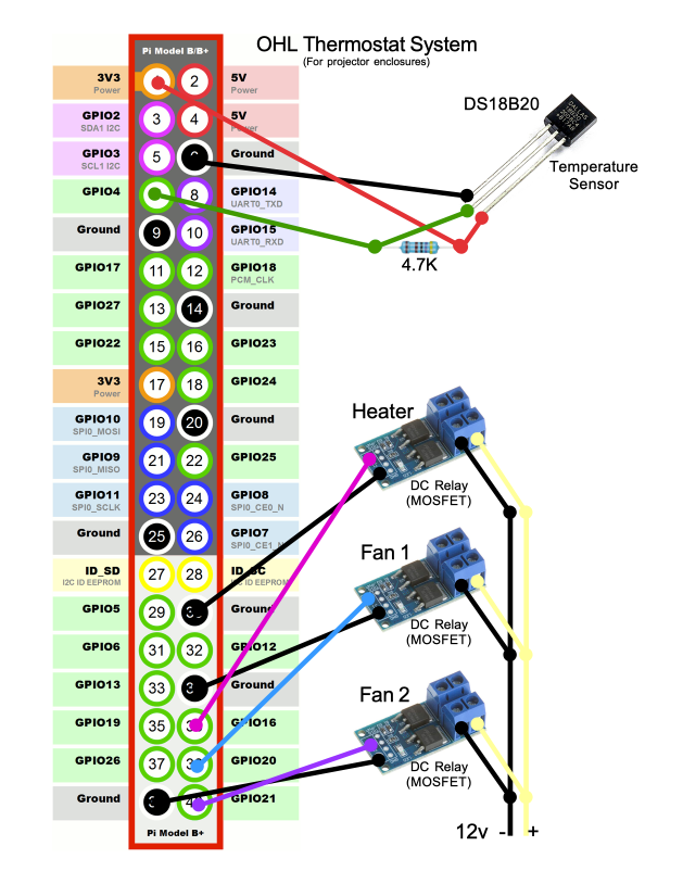
Basically you just need to wire 3v3 to leg 1. Leg 2 is the 1-Wire IO, which by default needs to go to GPIO4 on the RPi. Leg 3 is ground. You also have to add a 4.7㏀ pulldown resistor between Leg 2 and Leg 3. Internal pulldowns on the RPi won’t work. I just soldered jumper wires and the resistor to the legs per the diagram, wrapped the bare wires with Kaptan tape, and covered with shrink tub to make a durable little temperature sensor that I could tape or mount inside the enclosure. The wiring diagram and a picture of the prototype is later in this post. Once you have it hooked up, you need to…
Edit /boot/config.txt and add the following to the bottom:
dtoverlay=w1-gpioEdit /etc/modules and add the following to the bottom:
w1-gpio
w1-therm
Then reboot.
To read the temperature, you need to look in /sys/bus/w1/devices/ for a folder named for the DS18B20’s 1-Wire serial number. You will find a file called “temperature” there, that contains the ℃ temperature 1/1000ths. So, for example: /sys/bus/w1/devices/28-3c43e38183cb/temperature. This is a virtual file- reading it will query the DS18B20 for the current temperature and return it. Multiplying the returned value by 1000 yields the temperature in ℃, so 25426 => 25.426℃
So, now we have a temperature sensor and we can read the temperature. Now- we need to control the heater and fans…
You can use almost any logic-level input relay board for this. I had a bunch of these SSRs (MOSFETS) in-stock and decided to use them:
A MOSFET is a solid-state DC relay, and for our needs these will work great. They are opto-isolated and designed specifically for 3v logic triggering from a Raspberry Pi, Arduino, Node-MCU, etc. So, there is no need for a logic level converter or any other hardware.
UPDATE/WARNING:
The MOSFETs above are supposed to be rated at 15A without additional cooling. The heater is 12A, but the MOSFET board controlling it got extremely hot in testing. It scorched the PCB, melted/burned the Alien Tape holding it to the enclosure, and left a scorch mark where it was installed. If I hadn’t caught it, I believe it may have started a fire! I’m limiting these little MOSFETS to 5A now, regardless of what the specs say.
I also noticed that my usual DC power connectors were really heating up when the heater is on. While 16 AWG should be able to handle 12A, the load of the heater proved to be a bit too much for them.
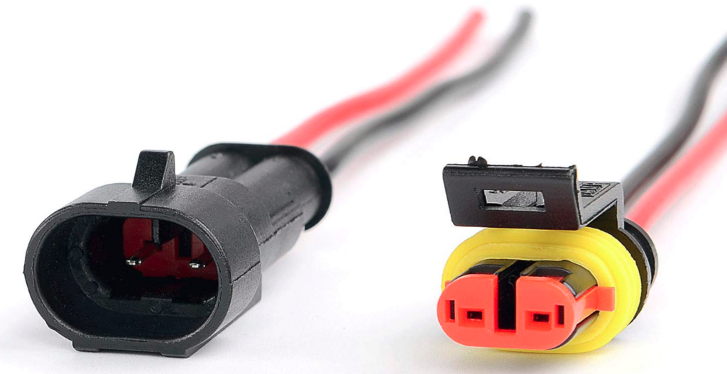
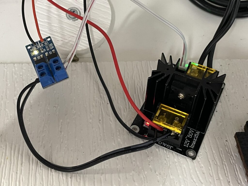
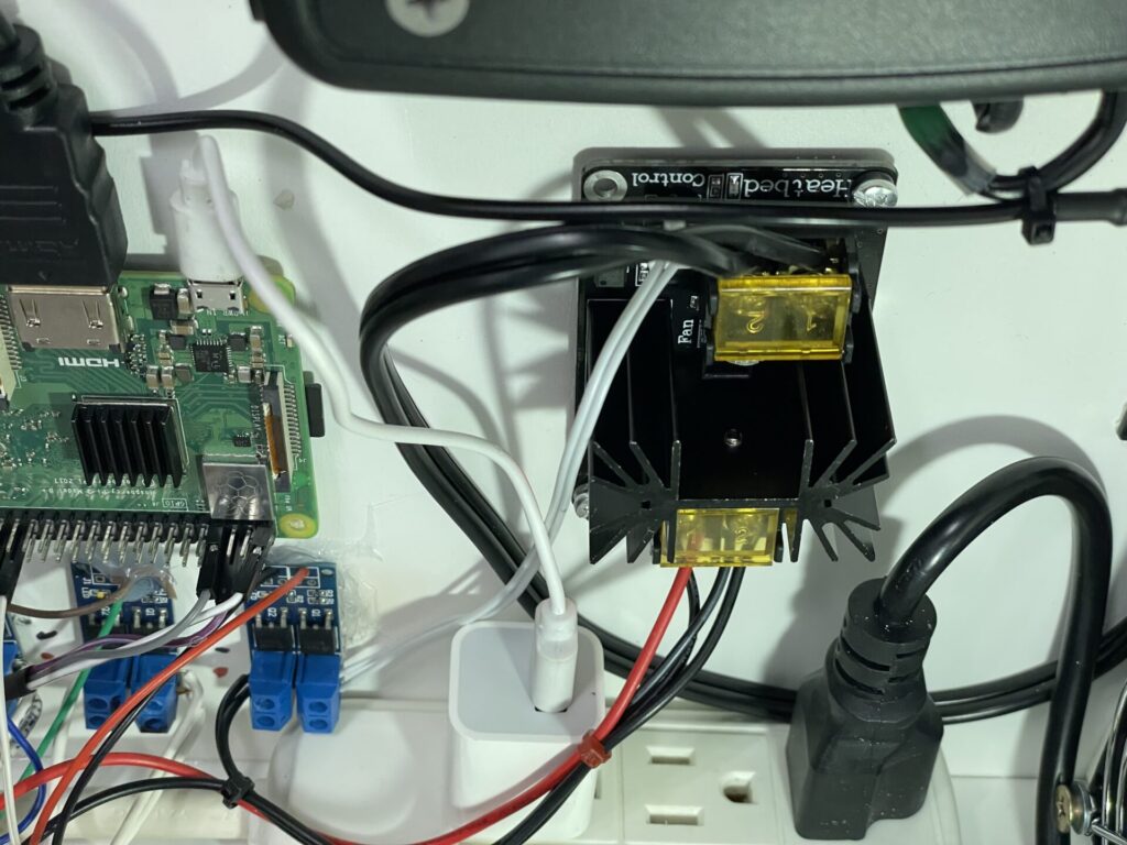
So, I added a much heftier MOSFET, similar to the ones I used to use in my 3D printers for powering the heated print bed. These can handle up to 25A and barely get warm when on. Because it has a 12v trigger, I’m using a smaller 3.3v trigger MOSFET to trigger the larger one. It works! I’m also upgrading the 12v power connectors for these high-current 12AWG SAE-style connectors, similar to trailer connectors. Both are linked below:
The small MOSFETS work great for the fans, so I don’t see any reason to replace them.
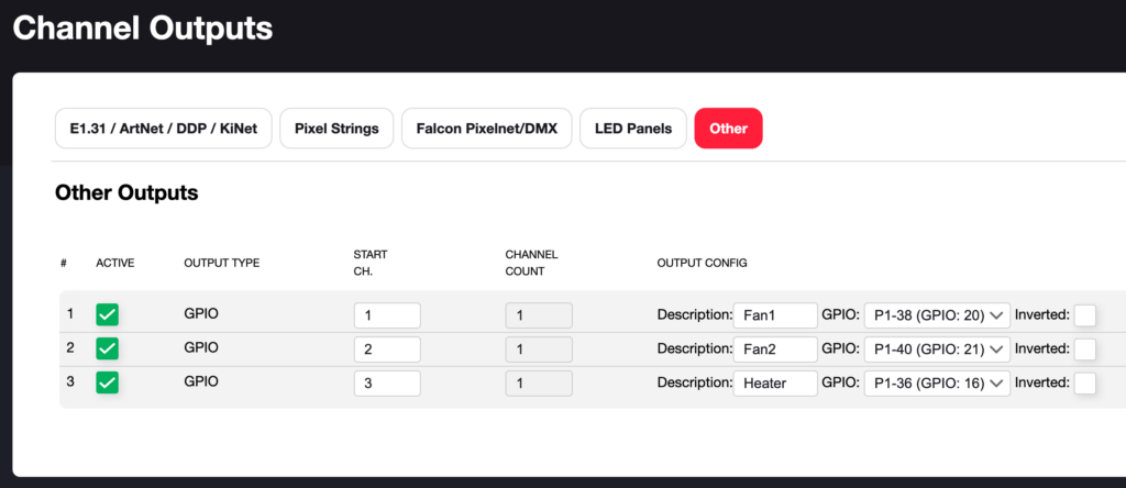
I decided to connect the MOSFETS to the following GPIOs:
Pin 36 (GPIO16) = Heater (High Current MOSFET)
Pin 38 (GPIO20) = Fan1 (MOSFET)
Pin 40 (GPIO21) = Fan2 (MOSFET)
I then set these up in FPP as Channel Outputs so I can control them with FPP, and using a script later:
To control the outputs via a script, I also needed to add them as Pixel Overlay Models too:
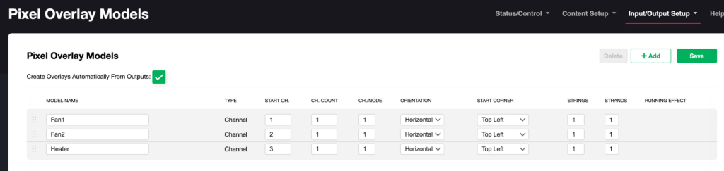
At this point- I can turn the fans and heater on and off using simple FPP scripts that toggle the Pixel Overlay Models. The goal, of course, is to completely automate it though, so…
I wrote a “thermostat.php” script that does just that. You can download it from GitHub here: https://github.com/neowolfwitch/fpp_scripts/tree/master/2023
The script is well-documented. You just need to edit it according to your own configuration and needs, and set it to automatically start on-boot in FPP, using the UserCallbackHook.sh script that you can install through the FPP Scrip Repository. This is documented in my script.
By default (as written), it polls the temperature probe every 15 seconds, then…
Fan 1 (primary vent fans) is turned on at 24℃ (75℉) and above.
Fan 2 (secondary vent fans) is turned on at 28℃ (82℉) and above.
The heater is turned on at 4℃ (39℉)and lower.
I also added an overheat prevention stage to it. If the temperature exceeds 38℃ (100℉) the system goes into a failsafe mode where it turns on all the vent fans and sends a shutdown command to the projector via FPP’s API and Projector Control plugin. All fans stay on and the projector stays shut down until the system is restarted. The error is logged as-well.
It also includes code to shut down the projector if there is no reading from the temperature sensor. This can happen if a configured RPi is updated with a new FPP-OS, which wipes out the 1Wire configuration. If this wasn’t included, the heater will stay on all the time. This was actually a good thing the first time it happened as it brought the above SSR and connector shortcomings to light before they caused a fire.
Here is a diagram of how everything is hooked up for this. The diagram does not include the larger SSR setup for the heater:
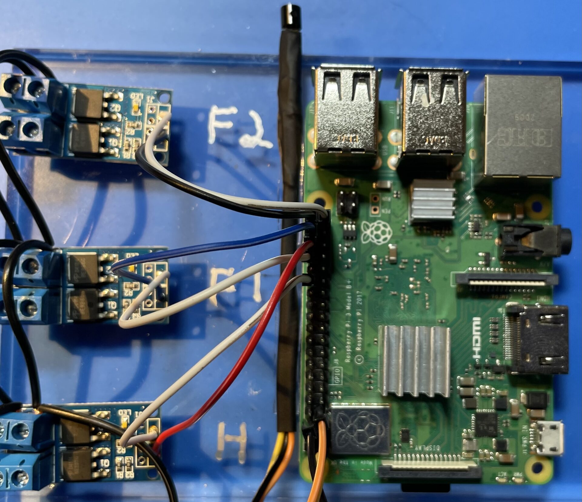
And here is the prototype:
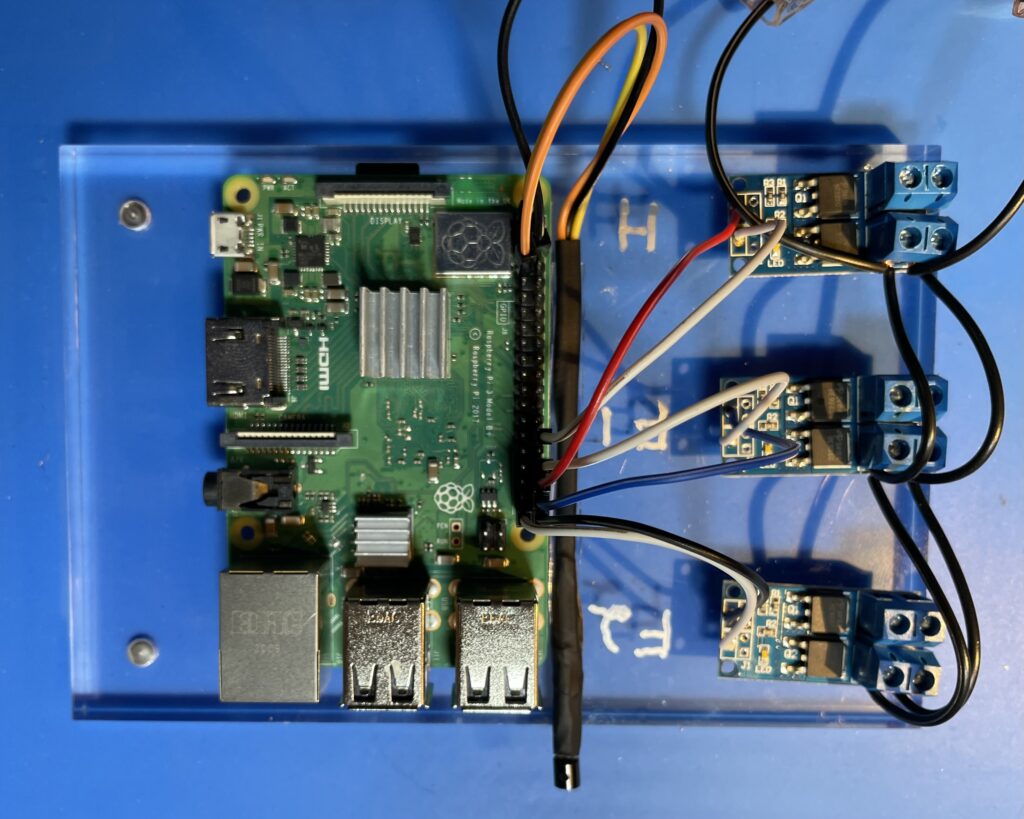
I built it upside-down from the diagram. Also- the wire colors are not the same. The temperature probe is right next to the RPi, with the sensor itself hanging off the edge. I tested this using ice, freeze spray, and various heat sources and it works as-expected. This will get installed in the new 2nd projector enclosure, and the Raspberry Pi for the 1st one will get loaded up with the same components and scripts.